|
|
Bachelor's Degree in Telecommunications Systems and in Network Engineering |
|
Legacy tools: Microchip ICD3/PICkit3 in-circuit debugger |
(1) Dual_MUX_4 (2) Counter_BCD_1digit (3) Adder_BCD_1digit (4) Counter_mod1572
| Prototype specifications | Planning | Development and Test & Measurements |
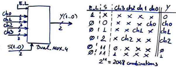
Let us adapt the circuit represented in Fig. 1 to the PICDEM2 board for the target chips: PIC18F4520. Specifications and ideas in LAB9.
 |
|
Fig. 1. Symbol and truth table. |
| Prototype specifications | Planning | Development and Test & Measurements |
This project is planned step by step in LAB9.
We will use the Windows 7 virtual machine with an older installation of MPLAB-X IDE and XC8 compiler. We choose the programmer tool simply as an option in the project.
Project location:
C:\CSD\LEGACY\Dual_MUX_4\PICDEM2p\(files)
| Prototype specifications | Planning | Development and Test & Measurements |
This project is developed in LAB9.
The same example (hardware and software source C code) for three microcontrollers:
-
PIC18F4520 --> Dual_MUX_4 (zip)
-
ATmega8535 --> Dual_MUX_4 (zip)
-
PIC16F877A --> Dual_MUX_4 (zip). A chip replacement for the PIC16F873A may the PIC16F883 also available in Proteus)
Example 1: Board Picdem2+, target microcontroller: PIC18F4520, tools: MPLAB X + XC8 + Proteus + PicKit 3 in circuit debugger/programmer.
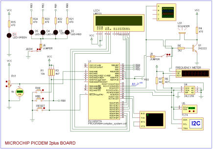 |
PICDEM2 simulated in Proteus-VSM Board with PIC18F4520 Demo default for the PIC16F877 (old board) |
ICD3 programmer

PICkit3

(1) Dual_MUX_4 (2) Counter_BCD_1digit (3) Adder_BCD_1digit (4) Counter_mod1572
| Prototype specifications | Planning | Development and Test & Measurements |
Let us adapt the circuit represented in Fig. 1 to the PICDEM2 board for the target chips: PIC18F4520.
Design phase #1: Basic counter
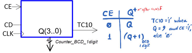 |
| Fig. 1. Symbol and function table as studied in Chapter 2. |
Design phase #2: Basic counter with LCD
Example 1: Board PICDEM2 PLUS. Target microcontroller: PIC18F4520. Tools: MPLAB X + XC8 + Proteus
Hardware circuit: "counter_BCD_1digit_LCD.pdsprj".
This is the proposed source code "counter_BCD_1digit_LCD.c" to be compiled with the LCD library functions.
Run the Proteus simulator. Do it in step by step mode while watching variables and placing break points, specially for following interrupt flags.
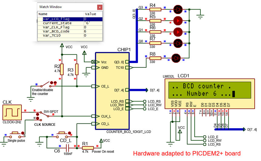 |
| Fig. 5. The circuit in "run" mode while monitoring the variables in the "watch" window. |
The idea is to download the application to a given training board to verify that the real product works as expected and the same as it was simulated.
This is the production file Counter_BCD_1digit_LCD_prj.X.production.hex that can be programmed directly using the IPE tool. We can use the prototyping area for soldering push-buttons, switches and LED.
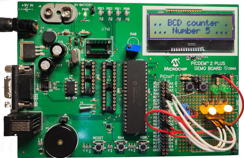 |
| Fig. 6. Prototype built on a PICDEM2 board. /p> |
Example 2 optional, beyond the CSD learning objectives. Board span class="auto-style102"> Explorer 8. Target microcontroller: PIC18F46K22. Tools: MPLAB X + XC8 + MCC + Proteus.
This is the implementation of the design phase #2: adding the LCD display to represent ASCII text. Explorer 8 LCD display is installed through an MCP23S17 16-Bit I/O expander with serial SPI Interface.
C:\CSD\P11\Counter_BCD_1digit_LCD\EXP8_PIC18F46K22\(files)
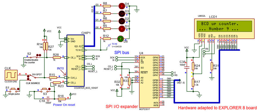 |
| Fig. 7. LCD running in Proteus simulations before downloading the executable to the Explorer 8 board. |
This is the adapted project counter_BCD_1digit_LCD.pdsprj and counter_BCD_1digit_X_LCD.zip.
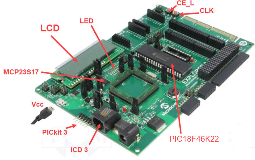 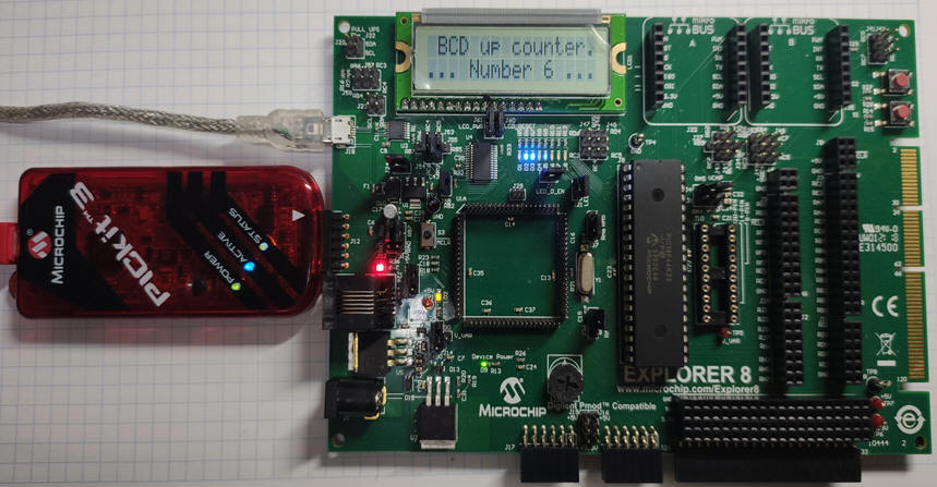 |
| FFig. 8. Prototype built on Explorer 8 board using the on board LCD. |
This is a project that can be used as a seed example for copying and adapting any other design. Peripherals are developed using the specialised software Microchip Code Configurator (MCC) representing a huge advantage.
Design phase #3: Basic counter with LCD and TMR0
| Prototype specifications | Planning | Development and Test & Measurements |
Design phase #1: Basic counter planned step by step in LAB10.
Design phase #2: Basic counter with LCD planned in
Design phase #3: Basic counter with LCD and TMR0
| Prototype specifications | Planning | Development and Test & Measurements |
This project is developed step by step in LAB10.
Board PICDEM2plus, target microcontroller: PIC18F4520, tools: MPLAB X + XC8 + Proteus + Pickit3 or ICD3 debugger/programmer.
We can use the prototyping area for soldering push-buttons, switches and LED.
Project location:
C:\CSD\LEGACY\Counter_BCD_1digit\PICDEM2p\(files)
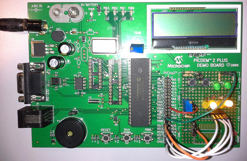 |
| Fig. 2. Prototype built on a PICDEM2 board. |
The complete project Counter_BCD_1digit.zip.
Example 2: Board PICDEM, target microcontroller: PIC18F46K22, tools: MPLAB X + XC8 + Proteus + MPLAB SNAP in-circuit debugger/programmer
We can try the same experiment using another target board and developing resources. Fig. 1 shows the adaptations for connecting a similar microcontroller. The hardware circuit "Counter_BCD_1digit.pdsprj" and the source file Counter_BCD_1digit.c so that we can pay attention on how to initialise configuration bits and ports for this specific target microcontroller PIC18F46K22.
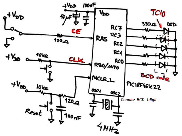 |
Fig. 1. Circuit connecting the PIC18F46K22. |
We can program and debug the circuit as we did already did in Proteus. Fig. 2 shows the setup using the MPLAB SNAP.
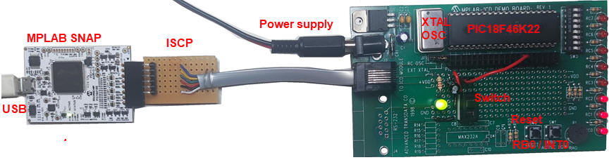 |
Fig. 2. Laboratory setup to verify our design. |
The prototyping are is quite limited, thus, is is a good idea is to make a target PCB connected through the expansion 40-pin connector. In this way the same PICDEM can be used repeatedly with different shields or protoboards to verify application circuits.
Example 3: Board Explorer 8, target microcontroller: PIC18F4520, tools: MPLAB X + XC8 + Proteus + PicKit 3 in circuit debugger/programmer.
The same project but changing the pins to adapt to port connections as shown in Fig. 1 and Fig. 2.
Project location:
C:\CSD\LEGACY\Counter_BCD_1digit\Exp8\(files)
 |
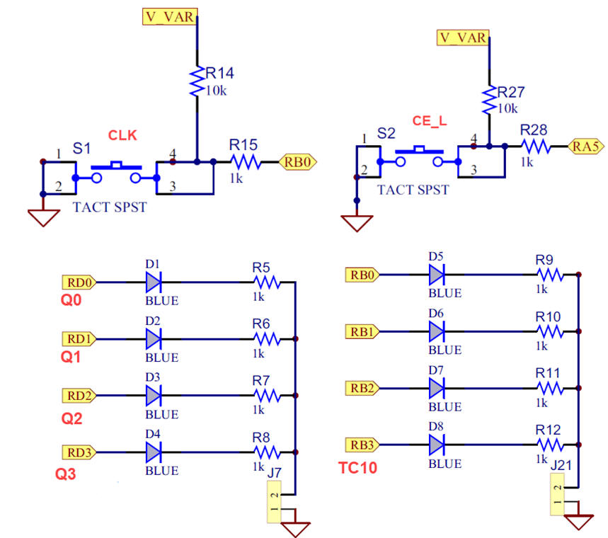
Fig. 1. Microcontroller pins for Explorer 8 board. Button S1 will generate external CLK interrupts. Button S2 will be CE_L control input. Schematic for COSC and MCRL_L are also represented pasted from the board's user manual. |
  |
|
The schematic connections are different thus hardware functions read_inputs() and write_outptuts() have to be modified accordingly. This is the advantage of programming the application using our style, only minor adaptations are necessary when changing prototyping platforms. This is the adapted project counter_BCD_1digit.pdsprj and counter_BCD_1digit.c.
The design can be also emulated in hardware using for instance ICD 3 tool monitoring variables, breakpoints, watch windows, etc.
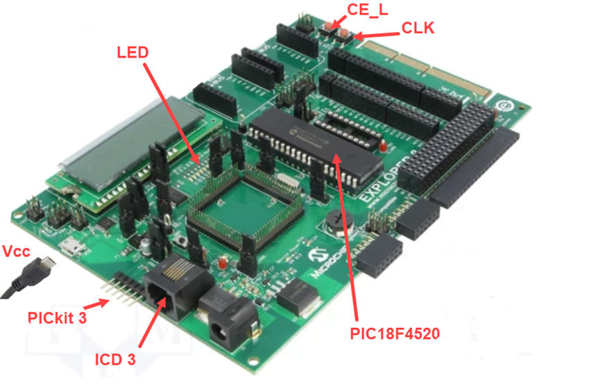 |
| Fig. 2. Prototype built on Explorer 8 board. |
Instrument such Analog Discovery 2 or VB8012 may be used to drive CLK signal using the waveform generator and measuring outputs connecting the logic analyser.
(1) Dual_MUX_4 (2) Counter_BCD_1digit (3) Adder_BCD_1digit (4) Counter_mod1572
| Prototype specifications | Planning | Development and Test & Measurements |
Let us adapt the circuit represented in Fig. 1 to the PICDEM2 board for the target chips: PIC18F4520.
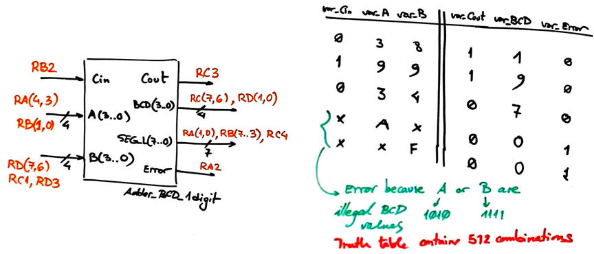 |
| Fig 1. Symbol of the 1-digit BCD adder indicating the port pins where to connect input and outputs. |
| Prototype specifications | Planning | Development and Test & Measurements |
This project is planned step by step in P9.
| Prototype specifications | Planning | Development and Test & Measurements |
This project is developed step by step in P9.
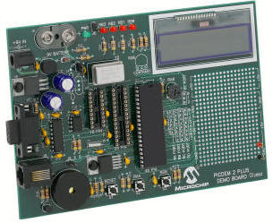
Example 1: Board Picdem2+, target microcontroller: PIC18F4520, tools: MPLAB X + XC8 + Proteus + + legacy PICkit3 in-circuit debugger-programmer.
|
|
Fig. 1. PICDEM2+ board to be used with a PIC18F4520 chip. Expansion connectors or prototyping area can be used to connect switches and LED. |
Note on peripheral libraries. To solve projects involving specialised and complex peripherals you have to rely on external libraries, and there are a variety of them for the same purpose, depending as well on the C compiler. For instance, when installing the PLIBS for the XC8 compiler you can access to a variety of libraries including enhanced LCD functions (XLCD). Try this example circuit where all the required functions and header files from PLIBs are copied in the project folder allowing you to compile and run.
Example 2: Board Explorer 8, target microcontroller: PIC18F4520, tools: MPLAB X + XC8 + Proteus + legacy PICkit3 in-circuit debugger-programmer.
(1) Dual_MUX_4 (2) Counter_BCD_1digit (3) Adder_BCD_1digit (4) Counter_mod1572
| Prototype specifications | Planning | Development and Test & Measurements |
Board PICDEM, target microcontroller: PIC18F46K22. Tools: MPLAB X + XC8 + Proteus MPLAB SNAP in-circuit debugger/programmer.
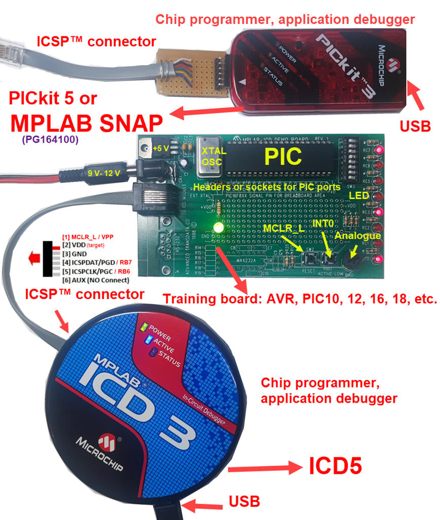 |
Fig. 1. (update) Basic elements for prototyping a microcontroller application. For new MPLAB X IDE versions, legacy tools and some target mC chips are no longer supported, thus you can choose the programmer/debugger to be ICD5 or PICkit 5 or MPLAB SNAP. |
| Home Term 26/27-Q1 Contact Products Electronic devices and companies Software Books Magazines Instruments DEE Library EETAC DEEL |

|
|
| Web activa des de 09/2001, @ F. J. Robert, Web editat amb Microsoft Expression Web 4. El contingut és un complement als materials d'estudi del curs Circuits i Sistemes Digitals disponibles al campus digital Atenea. Llicència:Reconeixement 4.0 Internacional de Creative Commons |