|
|
Bachelor's Degree in Telecommunications Systems and in Network Engineering |
|
|
|
|||
|
|
1-digit BCD counter with LCD and TMR1 (design phase #3) |
|
|
|
|
|||
FSM + plan X + Interrupts + LCD + TMR1 (as a timer with time from SOSC)
| 1. Specifications | Planning | Dev. & test | Prototype | report |
We will apply the TMR1 peripheral to replace the external CLK signal (design phase #3:
Replace the external CLK connected at INT0 (RB0) by the internal TMR1 to generate the same var_CLK_flag.
 |
| Fig. 1. Counter_BCD_1digit_LCD_TMR1 symbol using a secondary crystal oscillator connected as input to TMR1. |
| Specifications | 2. Planning | Dev. & test | Prototype | report |
A) Planning hardware
Let us use the free CSD_PICstick push-button to select between two CLK frequencies.
B) Planning software
For this application we have to select the secondary oscillator, and adjust N1 and N2 parameters to obtain the desired TP. For instance: TP = 1 Hz ==> N1 = 1, N2 = 32768. TP = 12 Hz ==> N1 = 1, N2 = 2731.
Software organisation is like in Counter_BCD_1digit_LCD_TMR0 replacing TMR0 by TMR1.
 |
| Fig. 2. How to configure TMR1 peripheral to generate a) 1 Hz or b) 12 Hz from the external 32.768 kHz secondary oscillator. |
NOTE: In order to avoid warnings and complications regarding project names and folder path length, we will shorten them.

Organise an MPLABX - XC8 IDE project targeting a PIC18F46K22 at location:
C:\CSD\P12\c_BCD_1d_LCD_TMR1\(files)
| Specifications | Planning | 3. Dev. & 4. test | Prototype | report |
A) Developing hardware
This is the Proteus circuit "Counter_BCD_1digit_LCD_TMR1.pdsprj".
B) Developing software
The XC8 compiler version is v3.0 or newer, C standard is C99. And these LCD library files "lcd.c", "lcd.h" has to be included in the project. The file "config.h" contains all the microcontroller configuration bits.
This is the source file: "Counter_BCD_1digit_LCD_TMR1.c".
C) Step-by-step testing
The counter is running using TMR1 interrupts driven by the secondary oscillator. Use breakpoints, watch window and follow the Program Counter to check how the microcontroller executes instructions.
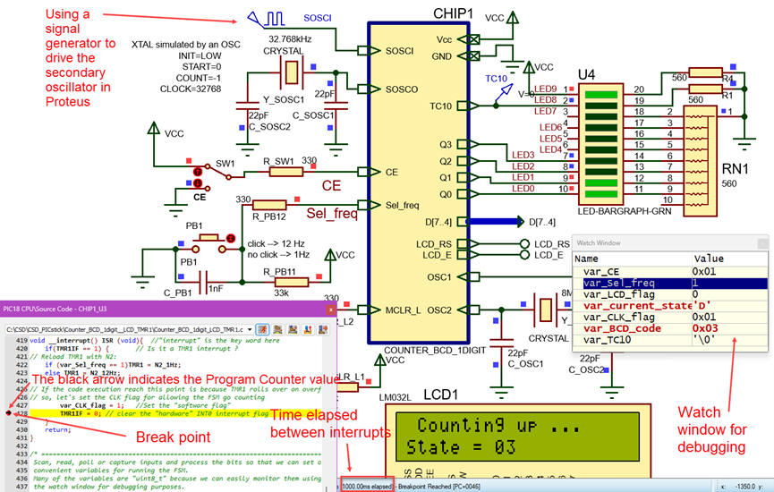 |
| Fig. 3. Circuit running. |
| Specifications | Planning | Dev. & Test | 5. Prototype | Report |
We have adapted the hardware so that we can mount the application using the PCD_PICstick.
| Specifications | Planning | Dev. & Test | Prototype | 6. Report |
Follow this rubric for writing reports.
| Home Term 26/27-Q1 Contact Products Electronic devices and companies Software Books Magazines Instruments DEE Library EETAC DEEL |

|
|
| Web activa des de 09/2001, @ F. J. Robert, Web editat amb Microsoft Expression Web 4. El contingut és un complement als materials d'estudi del curs Circuits i Sistemes Digitals disponibles al campus digital Atenea. Llicència:Reconeixement 4.0 Internacional de Creative Commons |