|
|
Bachelor's Degree in Telecommunications Systems and in Network Engineering |
|
|
|
MUX_8 plan B: behavioural flat single-file VHDL |
8-channel multiplexer
| 1. Specifications | Planning | Developing | Functional test | Gate-level test | Prototype | Report |
Design a MUX_8 with characteristics similar to the classic 74HCT151 chip in a programmable logic device (PLD) target chip following structural plan B using our VHDL design flow and EDA tools for developing and testing.
 |
 |
|
|
|
| Fig. 1. Symbol and truth table. | |

In Fig. 2 there is an sketch of timing diagram.
|
|
|
Fig. 2. Example of a timing diagram sketch to demonstrate how the circuit works for different inputs. Inputs will be translated to VHDL as stimulus signals in the simulation testbench. |

| Specifications | 2. Planning | Developing | Functional test | Gate-level test | Prototype | Report |
This flowchart explains the main concepts involved in VHDL design flow process.
 |
| Fig. 3. Plan B sequence of operations. |
Translate the truth table into an algorithm or flowchart (rec.) or schematic for capturing the complete truth table. As shown in Fig. 4 there are always several options to obtain a flowchart.
 (1) (3) |
| Fig. 4. Plan B flowchart interpretations of the truth table, versions (1) and (3). |
And several options as well to capture the complete truth table in a single statement.
 (2_1)  (2_2) |
| Fig. 5. Plan B truth table capture using schematics, versions (2_1) and (2_2) |
Each behavioural version will generate a different VHDL file, thus, adapt folder names for saving them:
C:\CSD\P2\MUX_8B1\(files)
C:\CSD\P2\MUX_8B2_1\(files)
C:\CSD\P2\MUX_8B2_2\(files)
C:\CSD\P2\MUX_8B3\(files)
| Specifications | Planning | 3. Developing | Functional test | Gate-level test | Prototype | Report |
Find in product a similar circuit designed using plan B with an architecture that corresponds to a truth table or algorithm to copy and adapt.
Translate your algorithm, flow chart or schematic into VHDL in a single file. Our planning shows up to four versions:
(1) "MUX_8.vhd" from the flowchart above.
(2_1) "MUX_8.vhd" from the schematic above.
(2_2) "MUX_8.vhd" from the schematic above.
(3) "MUX_8.vhd" from the flowchart above.
The entity name and VHDL description is related to the symbol in Fig. 1 and it does not depend on the architecture plan. It is always the same description in Fig. 6.
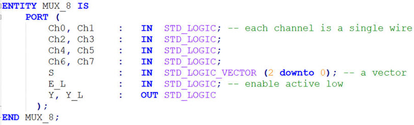 |
| Fig. 6. The entity description in VHDL is the same for all design plans. |
Start a new project in Quartus Prime, name it MUX_8_prj and select a target programmable chip (CPLD or FPGA) from our laboratory training boards. For instance, use Intel MAX II CPLD EPM2210F324C3, the same used above in plan A for better comparing circuit realisations.
 |
| Fig. 7. New project in Quartus Prime. |
Synthesise your circuit and examine results. Print, analyse and comment the computer generated RTL and technology views or schematics of the circuits.
 |
| Fig. 8. Example of RTL (click to expand). Why is this circuit such different from the one in plan A? |
As shown in Fig. 9, even for initial source VHDL files based on totally different plans, the same technology circuit is implemented for real in the target chip.
 |
|
Fig. 9. Example of technology view. How many resources (logic cells) are used? How different is this circuit from the one represented in plan A? |
Discuss advantages and drawbacks of plan A and plan B.
NOTE: To show you how practical is plan B in VHDL, this is the fast translation of the flowchart version for a "MUX_16.vhd".
| Specifications | Planning | Developing | 4. Functional test | Gate-level test | Prototype | Report |
To test the solution whatever it is from any plan, use the same test bench because even if you have invented different architectures, we use always the same entity under test. The testbench fixture containing the main ideas and concepts involved in this schematic is represented in Fig. 10.
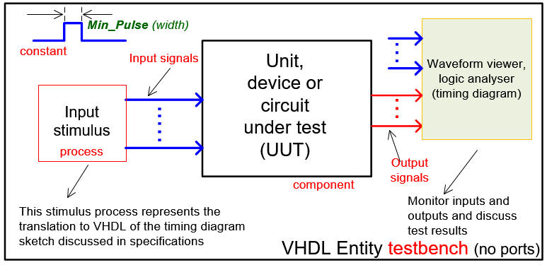 |
| Fig. 10. Testbench VHDL schematic. |
Generate from Quartus Prime the testbench template in Fig. 10. Rename it and move it to the project folder. Delete the empty process.
Translate the stimulus signals into a process and set the constant Min_Pulse in Fig. 4. This is a VHDL testbench example "MUX_8_tb.vhd" from which you can copy only the stimulus process and Min_Pulse constant.
Start an EDA VHDL simulator project to verify the device-under-test (DUT) using the VHDL simulator test bench.
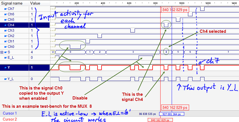
In Fig. 11 there is an example of commented test bench results from the logic analyser (wave) available in the EDA tool simulation tool. Use coloured pens.
 |
|
Fig. 13. Example of a timing diagram produced by the simulator with some mandatory comments and discussion on the way the circuit works. |
| Specifications | Planning | Developing | Functional test | 5. Gate-level test | Prototype | Report |
| Specifications | Planning | Developing | Functional test | Gate-level test | 6. Prototype | Report |
Install the DE10-Lite driver Altera USB-Blaster following the indications. It has to be identified as shown in Fig. 14 by the control panel's device manager.
 |
|
Fig. 14. Program the FPGA configuration file. |
Fig. 15 shows the Quartus Prime pin assignment tool spreadsheet. This "MUX_8_prj.csv" is the list of pins assigned as inputs and outputs in this project. It can be directly imported.
  |
|
Fig. 15. Pin assignment. The unused LED can be disabled connecting them to '0'. |
Program the "MUX_8.sof" to run the application as shown in Fig. 16 and verify both the circuit design and the hardware. As an alternative, you can make permanent the FPGA programming uploading the configuration flash (EPROM) memory (CFM) file: "MUX_8.pof".
 |
|
Fig. 16. Program the FPGA by means of the JTAG interface USB-Blaster tool. |
The next section presents a more elaborated demonstration prototype to start practising with laboratory instrumentation and measurements.
| Specifications | Planning | Developing | Functional test | Gate-level test | Prototype | 7. Report |
Follow this rubric for writing reports.
| Home Term 26/27-Q1 Contact Products Electronic devices and companies Software Books Magazines Instruments DEE Library EETAC DEEL |

|
|
| Web activa des de 09/2001, @ F. J. Robert, Web editat amb Microsoft Expression Web 4. El contingut és un complement als materials d'estudi del curs Circuits i Sistemes Digitals disponibles al campus digital Atenea. Llicència:Reconeixement 4.0 Internacional de Creative Commons |