|
|
Bachelor's Degree in Telecommunications Systems and in Network Engineering |
|
|
Using minilog.exe (output --> equations) |
||
Logic function minimisation based on ESPRESSO algorithms
1. Minilog installation
The software is installed and available at EETAC laboratories and computers. It can be easily installed in your computer as well in the same project folder where you like to use it.
 |
Fig. 1. Software Minilog |
2. An example circuit minimised using sum of products (SoP)
This is an example on the use of minilog to design a circuit based on minimised equations derived from the truth table. Fig. 2 shows Circuit_P truth table written using its canonical maxterms. The aim of this problem is to invent another circuit, for instance Circuit_Q, based on a SoP. There is another example below in section 3 to invent another circuit, for instance Circuit_R, based on PoS.
  |
Fig. 2. Specifications of a circuit: Symbol (vsd) and canonical equation using a product of maxterms. |
The minilog compatible "Circuit_P.tbl" text file that describes the circuit's truth table from Fig. 2 is represented in Fig.3. Let us assign them all a file extension tbl to be identified correctly as input files to minilog. Some of minilog reserved words are table, input, output and end.
 |
Fig. 3. Example truth table file ready for minilog. |
Copy the source file in your project folder, for instance: "L:\CSD\P1\Project_P\" and run the application. NOTE: 'L' or 'C' is your computer's hard drive root directory. In CSD you must always organise your directory tree from your hard drive root folder.
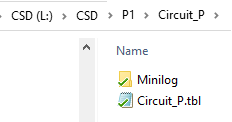 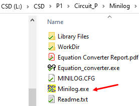  |
Fig. 4. Project and minilog folders.
The first time you run the applications a popup windows will block execution, so, click run anyway. |
Load "Circuit_P.tbl file and select minimisation parameters as shown in Fig. 5. This time, in order to generate the circuit_Q, choose minimisation result in sum of products (SoP) form.
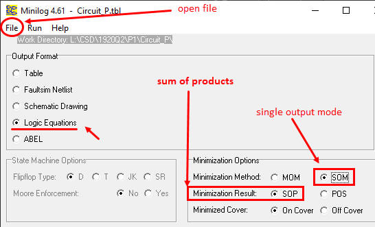 |
Fig. 5. Parameter selection. Single Output Mode (SOM) means that the minimiser will simplify an output at a time. Sum of products (SoP) is the expected result and output format "Logic Equations" means that the minimiser will write an equation. |
Execute the minimise order as in Fig. 6.
 |
Fig. 6. Click F9 or select minimise to start the process of minimisation. |
Inspect the minimisation result file "Project_P.equ" showing the equations.
 |
Fig. 7. Minilog result in equation format. You can realise how input and outputs variable names are replaced by A, B, C, etc. which is not convenient at all. |
The final step is the application equation converter developed by Gerard Nadal, so that the result will be in the right and desired form.
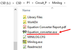 |
Fig. 8. Click and execute the equation converter program. |
Run "Equation_converter.exe" and the output processed file "Circuit_P_corrected.txt" will contain the equation in SoP form.
  |
|
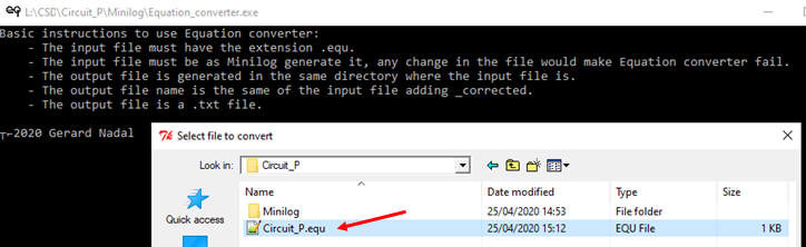
Fig. 9. Select the minilog output file Circuit_P.equ as the input for the Equation_converter.exe |
An equation that, if you like, can be easily translated to any other convenient form, for instance to VHDL.
Draw the Circuit_Q from this equation in Fig.9. To complete the project, now is time for checking that this equation produces the same truth table represented in Fig.2. You may use WolframAlpha or Proteus or VHDL to perform this test.
3. An example circuit minimised using product of sums (PoS)
This is the same example above in Fig. 2 on the use of minilog to design a circuit based on minimised equations derived from the truth table in the form of product of sums (PoS). The aim of this problem is to invent another circuit, for instance Circuit_R, based on PoS. Thus, Fig. 2, Fig. 3 and Fig. 4 are the same. Click the option PoS as shown in Fig. 8.
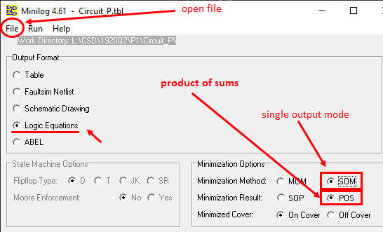 |
Fig. 10. Selecting minimisation result in form of an equation in PoS. |
Inspect in Fig. 11 the resulting file Circuit_P.equ showing the output equation in PoS mode.
 |
Fig. 11. Minimisation results from minilog in product of sums (PoS) mode. We have to apply Equation_converter as a final step to obtain the desired equation. |
Run the equation_converter and the output file "Circuit_P_corrected.txt" will contain the final equation in PoS form with the corresponding input and output ports defined in ur symbol.
 |
|
Fig. 12. Select the minilog output file Circuit_P.equ as the input for Equation_converter.exe |
Draw the Circuit_R from this equation in Fig.12. To complete the project it is time for checking that this equation produces the same truth table represented in Fig.2. You may use WolframAlpha, Proteus or VHDL to perform the test.
Other similar tutorial exercises
This was the former minilog tutorial where the table output format was interpreted to obtain minimised equations and so the Equation_converter tool was not necessary.
- Another complete example for minimising logic functions using Minilog (docx). Truth table example "HEX_7SEG_basic.tbl" The idea is always start with a file which already runs and modify it accordingly to the new problem truth table. Another truth table example which uses "don't care terms": "HEX_7SEG_all.tbl"
| Home Term 26/27-Q1 Contact Products Electronic devices and companies Software Books Magazines Instruments DEE Library EETAC DEEL |

|
|
| Web activa des de 09/2001, @ F. J. Robert, Web editat amb Microsoft Expression Web 4. El contingut és un complement als materials d'estudi del curs Circuits i Sistemes Digitals disponibles al campus digital Atenea. Llicència:Reconeixement 4.0 Internacional de Creative Commons |