|
|
Bachelor's Degree in Telecommunications Systems and in Network Engineering |
|
|
Blink_LED using FSM control flow and MCC Melody |
| 1. Specifications | Planning | Dev. & test | Prototype | Report |
Let us design A LED blinker using the MPLAB Code Configurator MCC Melody.
The final idea left for this third tutorial is to control the program flow using a FSM pattern, as we do in CSD. Reference from Microchip University on this idea.
-
External push-button ST_L connected to INT0 for turning the application ON-OFF.
-
Blink_timing resource from TMR0.
-
A switch P to choose 5 Hz or 200 Hz.
NOTE: Other versions of the same project:
Blink_LED: Using PIC18F and bare-metal register configuration in C language
Blink_LED: Using Arduino. DEE LAB5 Project #2.
Thus, you can compare and see what is different accordingly to the technology selected. For instance, in Arduino we have to use timing functions (millis() or micros() ) to generate the var_CLK_flag on polling, while here we have configured directly one of the timer peripherals to trigger real-time interrupts.
Symbol and waveforms.
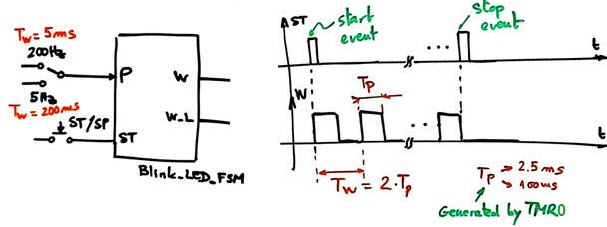 |
Fig 1. Blink_LED_FSM symbol and state diagram. |
| Specifications | 2. Planning | Dev. & test | Prototype | Report |
A) Planning hardware
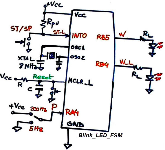
|
Fig 2. Blink_LED_FSM PIC18F46K22 connections. |
B) Planning software
To define a FSM, we have two options, and thus you can compare their features:
-
FSM style A: Use the CSD style to write the "Blink_LED_FSM.c". Take practically all of it from this project replacing the TMR1 by the TMR0 using the MCC.
FSM style B from Microchip University courses. Learn how to install the FSM structure from this guide on FSM design pattern.
We will start using Style A as in CSD. As shown in the state diagram, outputs at each state are represented in parenthesis and coloured red.
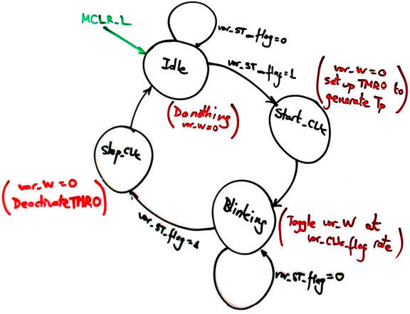 |
Fig 3. State diagram. |
| Specifications | Planning | 3. Dev. & 4. test | Prototype | Report |
A) Developing hardware
We can use some elements of the CSD_PICstick board modelled in Proteus as the hardware platform where to check our circuit.
Fig 4. Circuit captured in Proteus modelling the CSD_PICstick board. |
B) Developing software
The blinking timing resource is based on TMR0. N1 and N3 are configured in the MCC window. N2 will adopt two values to be selected with the switch P:
Setting the CLK times is solved applying the MCC-generated driver functions, as shown below:
The full project "Blink_LED_FSM.zip".
Use Proteus simulations or download the application to the CSD_PICstick.
Measure the signal W period TW. Why the frequency is lower than 200 Hz when selected? Solve the same project using bare-metal style and compare these features.
C) Step-by-step testing
| Specifications | Planning | Dev. & Test | 5. Prototype | Report |
| Specifications | Planning | Dev. & Test | Prototype | 6. Report |
|
Blink_LED with debounced ST_L button |
We can use this FSM Debouncing_Filter to clean the noise signal from the ST/SP push-button.
Now, the system responds to the ST_L click using the var_ST_debounced variable that is set only after the push-button signal is filtered. On the next state Start_CLK, while setting up the blinking CLK, the signal var_ST_ack is send to the debouncer, so that it can be initialised once the user has released the button.
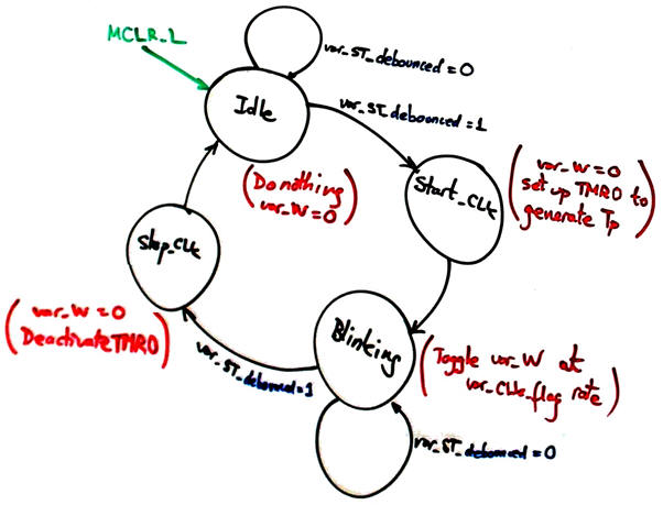 |
Fig 1. Modified Blinking_LED_FSM state diagram. |
We can use the same timing resource, such TMR0 for both FSM, or better, we can assign to each FSM a different timer, one for generating the blinking waveforms, and the other for sampling the ST_L while debouncing. MCC will facilitate such hardware adaptations.
Fig 2. Hardware-software diagram to visualise the location of each FSM and the complete system. |
| Home Term 25/26-Q1 Contact Products Electronic devices and companies Software Books Magazines Instruments DEE Library EETAC DEEL |

|
|
| Web activa des de 09/2001, @ F. J. Robert, Web editat amb Microsoft Expression Web 4. El contingut és un complement als materials d'estudi del curs Circuits i Sistemes Digitals disponibles al campus digital Atenea. Llicència:Reconeixement 4.0 Internacional de Creative Commons |