|
|
Bachelor's Degree in Telecommunications Systems and in Network Engineering |
|
|
Blinking LED using PIC and bare-metal programming |
| 1. Specifications | Planning | Dev. & test | Prototype | Report |
Design a LED blinker using PIC and bare-metal programming style. This project is also the step #1 for the Dimmer design phase #B.
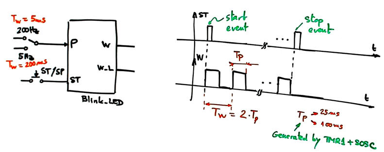
Include the FSM installation, W, W_L outputs, start- stop active-low ST_L push-button driven by interrupts (INT0), SOSC and TMR1 to generate a CLK signal for blinking the output at the required TP. Add a switch P to select two frequencies (5 Hz, 200 Hz).
|
|
|
Fig. 1. Blinker with ON/FF button ST and frequency selection switch P. |
NOTE: Other versions of the same project:
Blink_LED: Using PIC18F and Arduino
Blink_LED: Using PIC18F and MCC Melody
In this way we can observe how the main ideas and concepts for specifying and planning are very similar even if the final product is implemented using different technologies and tools.
| Specifications | 2. Planning | Dev. & test | Prototype | Report |
Hardware
|
|
Fig. 2. Hardware adapted to the CSD_PICstick. The switch to fix the timing period P is connected to RA4. |

Software
Hardware-software diagram, RAM variables, state diagram, FSM, interrupts, state logic, output logic.
|
|
Fig. 2. Hardware-software diagram and RAM variables. |
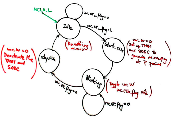
To run a FSM we have to imagine the situations in which the application will be working. Idle from a reset (MCLR_L), configuring the TMR1 once the start click is detected, blinking forever the LED until the stop click is detected, and finally, disabling all the circuit resources before going back to Idle.
|
|
Fig. 3. State diagram. In blinking state, the variable var_W will toggle at the rate imposed by TMR1 interrupt (var_CLK_flag). Before stopping the machine, the resources will be liberated. |
TMR1 has to be reloaded immediately at the interrupt service routine once the overflow flag TMR1IF is acknowledged.
|
|
Fig. 4. Interrupts for capturing the external ST_L falling edge event (var_ST_flag) and also the periodic TMR1 overflow event (var_CLK_flag). |
|
|
Fig. 5. State logic truth table and flowchart |
|
|
Fig. 6. Output logic truth table and flowchart |
Two coding styles or design patterns for control flow:
Style BM: bare-metal as in CSD Chapter 3, FSM and direct configuration of the PIC peripheral registers.
Project location accordingly to the option and style:
C:\DEE\Dimmer\PhB_OP2\BM\Blink_LED\(files)
Style MCC: using MPLAB Code Configurator (MCC) Melody tool and using the FSM control flow.
Project location accordingly to the option and style:
C:\DEE\Dimmer\PhB_OP2\MCC\Blink_LED\(files)
We will use MCC Melody to configure the system and its peripherals, keeping the application in the top PWM.c file.
| Specs | Planning | 3. Dev. & 4. Test | Prototype | Report |
Hardware
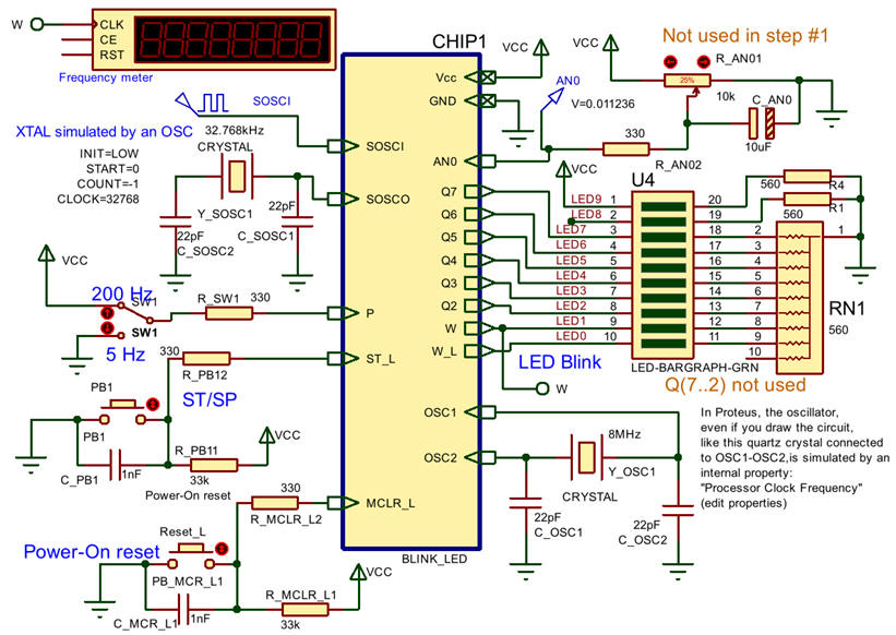
The circuit capture in Proteus will be done taking advantage of the adaptation of the CSD_PICstick board. Even if schematic in Fig. 7 contains resources available in the CSD_PICstick board but not used in this design step #1.
|
|
Fig. 1. Circuit captured in Proteus ready for simulations. |
Software
Style BM: Project files: "Blink_LED.zip".
Simulation in Proteus.
|
|
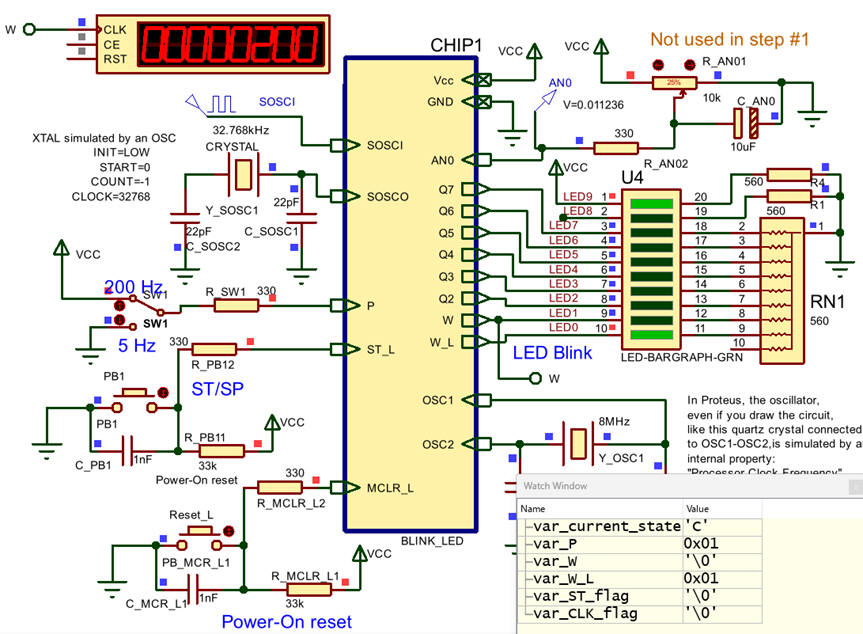
Fig. 1. Circuit running in Proteus while watching variables. Remember that you can measure timing periods using breakpoints placed at the interrupt service routine. |
Style MCC: Project files: "Blink_LED.zip".
| Specs | Planning | Dev. & Test | 5.Prototype | Report |
Experiment with the circuit programming the CSD_PICstick. Verify that both programming styles work correctly.
| Specs | Planning | Dev. & Test | Prototype | 6. Report |
| Home Term 26/27-Q1 Contact Products Electronic devices and companies Software Books Magazines Instruments DEE Library EETAC DEEL |

|
|
| Web activa des de 09/2001, @ F. J. Robert, Web editat amb Microsoft Expression Web 4. El contingut és un complement als materials d'estudi del curs Circuits i Sistemes Digitals disponibles al campus digital Atenea. Llicència:Reconeixement 4.0 Internacional de Creative Commons |