|
|
Bachelor's Degree in Telecommunications Systems and in Network Engineering |
|
Chapter 3 problems |
- D3.8 - |
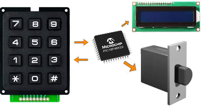
Electronic keypad lock (µC - C) |
1. Specifications
Let us design an electronic key pad lock using the PIC18F46K22 µC with the following features:
- 3-digit secret code using the symbols 0, 1, ..., 9, *, #.
- The symbols must be clicked in less than 15 s. 5 s maximum between symbols.
- Three consecutives invalid codes generate an alarm tone of 3.2 kHz and blocks the keypad. A second secret code must be used to resume normal operation.
- An LCD screen is used for representing "***" when the used is clicking, and other messages such "door locked", "door open" "alarm", etc.
  |
|
Fig. 1. The idea of an electronic keypad lock. Symbol and suggested connections to start the design phase #1. |
A similar project is proposed designed using only hardware in D2.8. References about these concepts and commercial products are everywhere, for instance: https://www.nokey.com or https://www.embedded.com/using-finite-state-machines-to-design-software.
Typical lock usage: (1) Power ON, do nothing (idle); (2) Capture and represent as "-" the inputted symbols on the display; (3) compare to the secret code; (4) Open the door for 2 s or keep it closed; (5) count the user trials and when four, activate the system alarm (a 1.4 kHz audible tone to a buzzer) and block the keypad to enter in disabled mode.
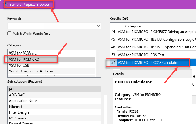
Proteus includes several calculator circuits for microcontrollers, and this project is not that different to what may be a simple calculator that you can analyse to get ideas. However, because the specific goal of this assignment is to learn the course content, we will follow our CSD plan imagining the circuit as a dedicated processor controlled by a FSM to govern the capturing of input data (user pin), the comparison operation and the output of symbols in 7-segment displays or an LCD screen.
 |
|
Fig. 2. Open and play with a Proteus sample project on calculators. |
2. Planning
Let us build the product organising several design phases, and several steps within each phase.
Design phase #1: basic features
Solve the circuit for the design step #1. Only when it is fully tested working correctly and reported, solve the design step #2.
- Design step #1. Keypad encoder.
The encoder may be: (A) type Enc_16_4, or (B) type P6 Matrix_encoder_16key. Choose your preference, even though we recommend the matrix keyboard to practice Chapter 2 materials. This is the "matrix_keypad.pdsprj" model.
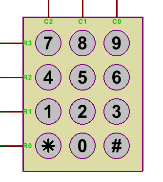 |
| Fig. 3. Modelling and simulating the matrix keypad in Proteus helps to comprehend the task the FSM must perform to encode the key pressed. |
Certainly, a subproject for this design will be interface to the matrix keypad, the idea if scanning rows and reading columns, it will be used for reading one key at a time when required by the application. This Matrix_encoder_16key is a tutorial on such design.
Project location:
C:\CSD\P10\eLock_s1\(files)
Project source files: "eLock.pdsprj", "eLock.c"
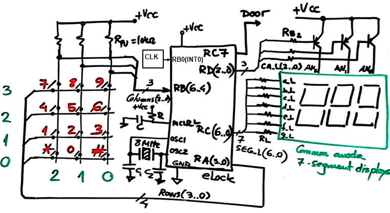
a) Draw the hardware schematic necessary for step #1.Include the 12-key keypad, an external CLK oscillator (320 Hz), 3-digit multiplexed BCD outputs, reset circuit MCLR_L and an 8 MHz quartz crystal oscillator. Explain how to configure the inputs and outputs in init_system().
What pins will be read? How many external interrupts are required in this step#1?
b) Draw the hardware/software diagram indicating the required RAM variables.
c) Draw the state diagram indicating state transitions and outputs. Fig. 4 shows some initial ideas on how to organise calculator operations in a similar way we have implemented other similar circuits in VHDL or C.
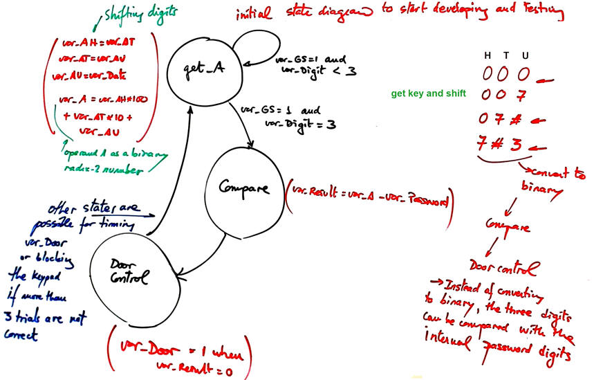 |
| Fig. 4. Example state diagram to start developing and testing in Proteus. |
d) Draw the truth tables and their equivalent flowcharts for state_logic() and output_logic() functions.
e) What is the interrupt service routine ISR() used in this application? Draw its flowchart.
f) Develop and test (debugging) the project capturing the hardware circuit in Proteus and writing the C source code. You must use the watch window to monitor RAM variables from the very beginning. Remember: one step at a time to be sure that your hardware and software works as planned.
- Design step #2. 3-digit MDS to represent the sign "-" (segment g) when the secret code is inputted or the messages "door ON" and "off"
Copy the step #1 hardware and source software files into de new location.
Project location:
C:\CSD\P10\eLock_s2\(files)
Project source files: "eLock.pdsprj", "eLock.c"
a) Draw the hardware schematic necessary for step #2. Explain how to configure it in init_system().
Explain what is new in sections b), c), d), e), f)
Develop and test the new feature in Proteus. Indeed, applying teamwork you can tackle both design steps simultaneously because the operands and results to be multiplexed may be simulated variable values.
Design phase #2: LCD display
Let us add an LCD display as studied in P11 to this application. The idea is to replace the MDS by the LCD to represent operands and results as ASCII characters on the screen.
Project location:
C:\CSD\P11\eLock\(files)
Project source files: "eLock_LCD.pdsprj", "eLock_LCD.c"
g) Enhance the schematic from the previous design phase #1 to replace the 7-segment digits and to include an LCD attached to PORTD as studied in tutorials.
h) Enhance the software and the source file to drive the LCD.
In this design phase you can learn the LCD interface step by step. For instance:
Design step #1. Print ASCII messages on the LCD. For instance "Door CLOSED", "Door OPEN", etc.
Design step #2. Print numeric information such the seconds down-count until the lock is blocked.
Develop and test the new feature.
Design phase #3: Using TMR2 peripheral subsystem
The 3.2 kHz external CLK is replaced by the internal 8-bit TMR2 peripheral to generate interrupts (TMR2IF). Discuss the main features of this peripheral and its applications.
Project location:
C:\CSD\P12\eLock_LCD_TMR2\(files)
Project source files: "eLock_LCD_TMR2.pdsprj", "eLock_LCD_TMR2.c"
i) Calculate TMR2 parameters required to generate the same 320 Hz keypad scan frequency. In this way the external CLK signal can be eliminated.
Develop and test the new feature.
Optional. If the keypad blocks after four unsuccessful trials, discuss how to unblock it using another security secret code.
| Home Term 26/27-Q1 Contact Products Electronic devices and companies Software Books Magazines Instruments DEE Library EETAC DEEL |

|
|
| Web activa des de 09/2001, @ F. J. Robert, Web editat amb Microsoft Expression Web 4. El contingut és un complement als materials d'estudi del curs Circuits i Sistemes Digitals disponibles al campus digital Atenea. Llicència:Reconeixement 4.0 Internacional de Creative Commons |