|
|
Bachelor's Degree in Telecommunications Systems and in Network Engineering |
|
Lecture 4 |
L2.4: Electrical characteristics: driving LED from digital outputs [P2] Seven-segment decoders (HEX_7seg_decoder), plan A, plan B |
[29 Sep] |
1.6.5. Driving LED
This "Circuit_logic_levels.pdsprj" is a circuit to play with LED, and to observe how when a logic gate is sinking too much current, the voltage levels are degraded. Measure voltage levels, currents, power consumption and logic values.
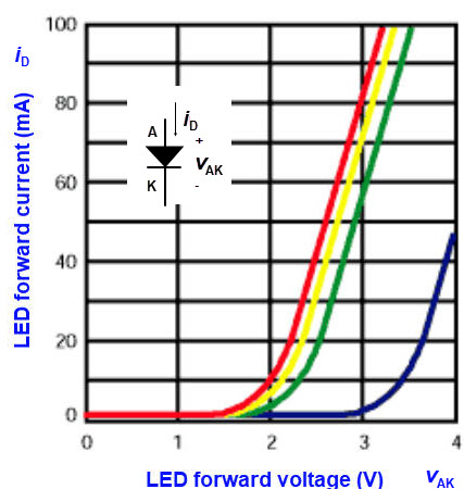
1.6.5.1. LED biasing characteristics.
1.6.5.2. Active-low and active-high outputs
1.6.5.3. Limiting resistor for worst-case scenario
How to drive LED from logic gates? rec.
Fig. 1 shows some typical LS-TTL values to consider when modelling inputs and outputs at DC or low frequency of operation. Gate outputs are equivalent to voltage sources with typical VOH or VOL margins.
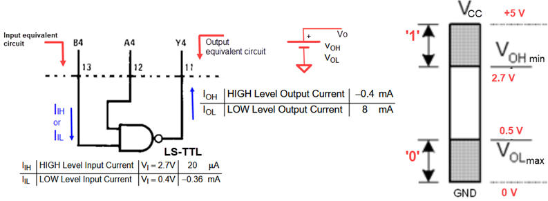 |
| Fig. 1. Typical input and output current values for LS-TTL family. |
Two circuits are possible: active-high (common cathode LED) and active-low (common anode LED).
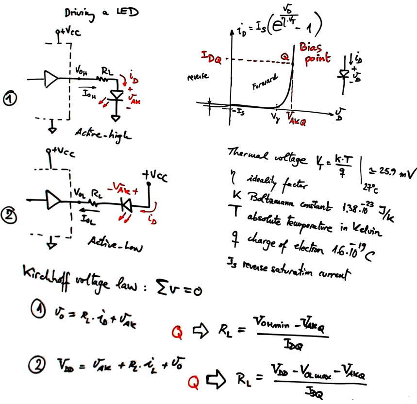 |
| Fig. 2. Driving a LED active-high and active-low and calculating limiting resistors. The idea is to guarantee the LED bias point Q (IDQ, VAKQ) even in the worst case scenario. |
For instance, selecting a Rohm semiconductor SMT LED SML-P11VTT86(R) and using CMOS or TTL-LS buffers or inverters:
 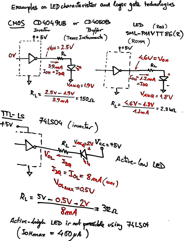 |
| Fig. 3. Example values. Use Proteus simulations or protoboards to demonstrate such results in the laboratory. |
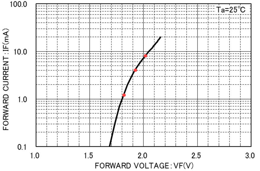
This is another typical LED datasheet.
This is another version of Circuit_W in Proteus where you can add to Chip1 some buttons, switches, LED's and even relays and motors. Play with the circuit and pay attention to the real voltages and currents that represent '0' and '1' signals.
 |
|
 |
|
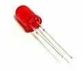
| Fig. 4. Standard red LED and typical green 7-segment displays. |
How to drive high-voltage and high current power LED ?
1.6.6. Driving 7-segment displays
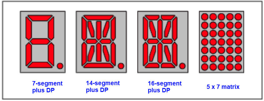 |
| Fig. 5.Several common types of segment and dot displays. Green 7-segment display |
1.6.6.1. Common anode digits
1.6.6.2. Common cathode digits
1.6.6.3. Multiplexed operation
1.7.6. Hexadecimal to 7-segment decoder (P2) Hex_7seg_decoder
1.7.6.1. Basic decoder as standard component
It is a circuit to drive the typical 7-segment displays. Run the circuit "Dec_hex_7seg.pdsprj" in Proteus to figure out how it works and infer its truth table.
1.7.6.2. Control signals: blanking (BI), ripple blanking (RBI, RBO), lamp test (LT)
1.7.6.3. Commercial chips
Type 74LS47 (active-low outputs for common anode display), HEF4511B (active-high outputs for common cathode display), etc.
1.7.6.4. Design examples
And, again, two alternative and systematic design plans are presented:
- Plan A. HEX_7seg_decoder . Using a structural approach based on minimised equations (SoP / PoS).
- Plan B. HEX_7seg_decoder. Using a behavioural (high-level) description (truth table or algorithm) approach.
Activity #1: Calculate the limiting resistor RL of a common anode LED circuit for both technologies CMOS (VDD = 9 V) and LS-TTL (VCC = 5 V). The bias point is IDQ = 6 mA, VAKQ = 2.1 V.
Simulate the circuits in Proteus to verify the LED bias point when lighting (use voltmeter and ammeter).
Remember that a project as a class activity requires this initial work:
(1) Specs & theory on electrical characteristics: Logic families, voltage and noise margins, currents, simulation models, LED bias point, etc.

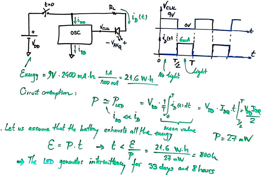
If the CMOS circuit is powered by a 9V - 2400 mAh Ni-MH rechargeable battery, how long is going to last if the CMOS circuit driving the LED is generating a 10 Hz intermittent square wave?
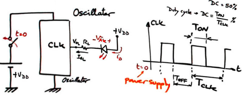
Discussion: For a quick and approximate calculation, let us imagine that the battery exhausts all the stored energy before shutting down the voltage. Additionally, we will consider that the CMOS circuit quiescent current is far lower that the LED bias current.
This question serves as a good example of how any activity in this subject can evolve into a full project. After this initial estimation, you can go deeper, trying to solve many more questions by studying real batteries and their corresponding charging circuits. Do batteries fully deplete their energy during normal operation, or do they preserve battery life by shutting down and leaving a certain percentage of stored energy? Additionally, can you design a 9 V - 2400 mAh rechargeable battery system to prototype and characterise in the lab? What kind of instrument testbench can be prepared to measure battery live?
| Home Term 26/27-Q1 Contact Products Electronic devices and companies Software Books Magazines Instruments DEE Library EETAC DEEL |

|
|
| Web activa des de 09/2001, @ F. J. Robert, Web editat amb Microsoft Expression Web 4. El contingut és un complement als materials d'estudi del curs Circuits i Sistemes Digitals disponibles al campus digital Atenea. Llicència:Reconeixement 4.0 Internacional de Creative Commons |