|
|
Bachelor's Degree in Telecommunications Systems and in Network Engineering |
|
|
|
Design Circuit_W |
Canonical equations plan A |
Minimised equations plan A |
plan B |
plan C2 |
| 1. Specifications | Planning and developing | Testing | Report | Prototype |
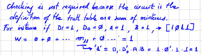
Using Circuit_W truth table written in Fig. 1 draw the two canonical versions of the circuit using gates (plan A):
-
W1: Circuit based on product of maxterms.
-
W2: Circuit based on sum of minterms.
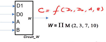 |
Fig. 1. Circuit_W symbol and truth table. |
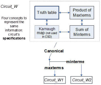 |
Fig. 2. Circuits W1 and W2 from the canonical equations of Circuit_W. These equations represent the same concept as the truth table. |
| Specifications | 2. Planning and 3. Developing | Testing | Report | Prototype |
Circuit_W1
Location for this project files, for instance: pictures, scanned files, report, etc. at:
C:\CSD\P1\Circuit_W\Circuit_W1\
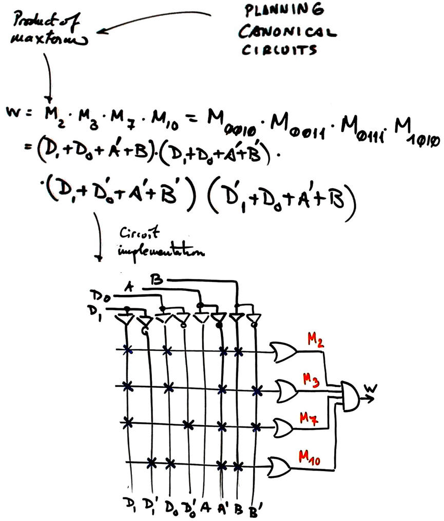 |
Fig. 3. Immediate circuit representing the product of all maxterms. |
Circuit_W2
Location for this project files, for instance: pictures, scanned files, report, etc.
C:\CSD\P1\Circuit_W\Circuit_W2\
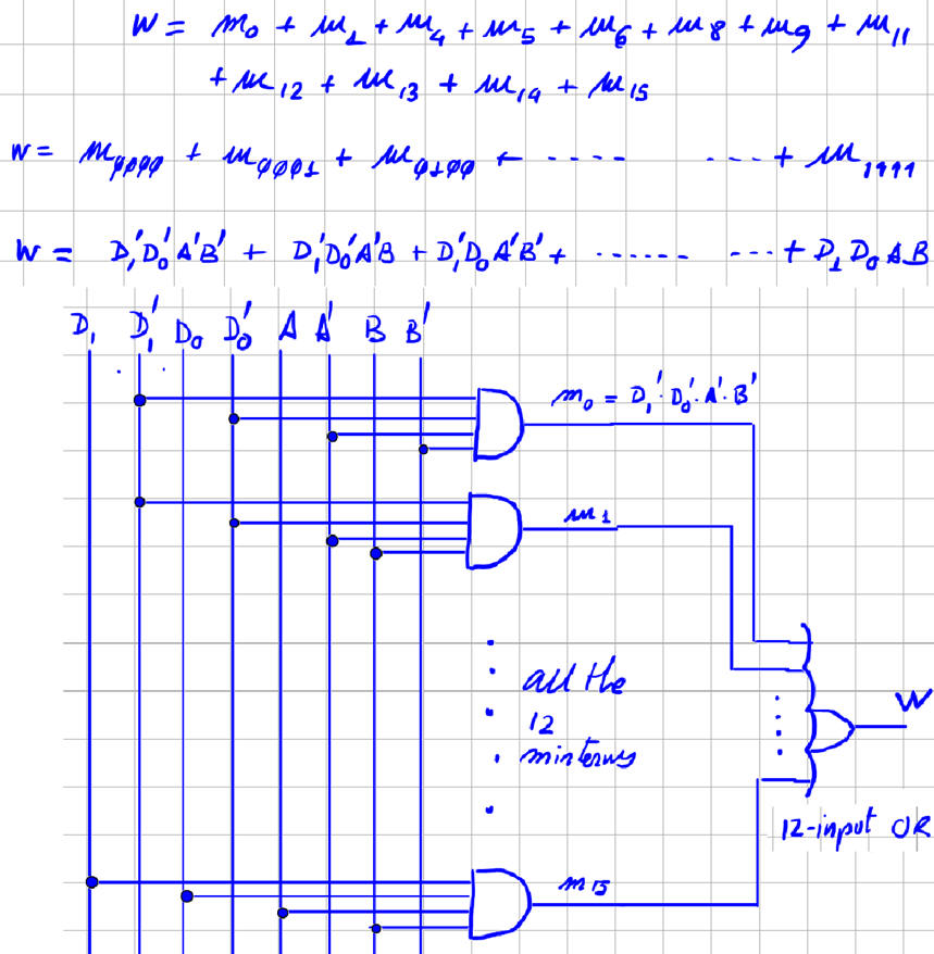 |
Fig. 4. Immediate Circuit_W2 representing the sum of all minterms. |
| Specifications | Planning and developing | 4. Testing | Report | Prototype |
If you test the circuit for example using WolframAlpha or Proteus you will place in the project folder your computer files such as "equations_W.txt" or "Circuit_W.pdsprj". However, in this case:
| Specifications | Planning and developing | Testing | 5. Report | Prototype |
Follow this rubric for writing reports.
| Specifications | Planning and developing | Testing | Report | 6. Prototype |
We can use the DE10-Lite board to implement this project in a similar way shown in this analysis tutorial Circuit_W. You only have to replace the architecture equation by the equation based on product of maxterms.
|
|
Design Circuit_W |
Canonical equations plan A |
Minimised equations plan A |
plan B |
plan C2 |
| 1. Specifications | Planning | Developing | Testing | Report | Prototype |
The same symbol and truth table. Design equivalent circuits based on
-
W3: Circuit based on SoP
-
W4: Circuit based on PoS
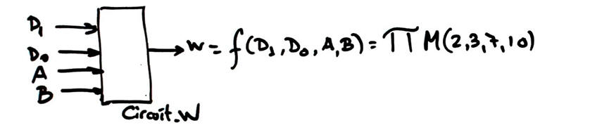 |
Fig. 1. Symbol and truth table as a product of maxterms. |
| Specifications | 2. Planning | Developing | Testing | Report | Prototype |
This time, we well use the minimiser tool minilog.exe
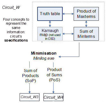 |
Fig. 2. Circuits W3 and W4, minimised equations from the Circuit_W truth table. |
Circuit_W3
This is the procedure to obtain results and complete the project:
1. Circuit_W3 project location:
C:\CSD\P1\Circuit_W\Circuit_W3\(files)
2. Find and modify a similar tbl file, fr example you can use the file "Circuit_P.tbl" in minilog tutorial and rename and adapt it to: "Circuit_W.tbl"
3. Run Minilog and simplify using single output mode (SoM), equation output format, and choose SoP.
4. Equation format that has to be reprocessed by equation_converter.exe so that you get SoP equation with the project entity names for inputs and outputs.
5. Draw the circuit.
6. Check the circuit's equation using WolframAlpha or Proteus.
| Specifications | Planning | 3. Developing | Testing | Report | Prototype |
Minilog file describing the truth table: "Circuit_W.tbl"

| Specifications | Planning | Developing | 4. Testing | Report | Prototype |
Test means verifying that the circuit that you have designed has the given initial truth table. For instance, this is the Proteus capture: "Circuit_W.pdsprj".

| Specifications | Planning | Developing | Testing | 5. Report | Prototype |
Follow this rubric for writing reports.
| Specifications | Planning | Developing | Testing | Report | 6. Prototype |
We can use the DE10-Lite board to implement this project in a similar way shown in this analysis tutorial Circuit_W. You only have to replace the architecture equation by the equation based on SoP.
| Home Term 26/27-Q1 Contact Products Electronic devices and companies Software Books Magazines Instruments DEE Library EETAC DEEL |

|
|
| Web activa des de 09/2001, @ F. J. Robert, Web editat amb Microsoft Expression Web 4. El contingut és un complement als materials d'estudi del curs Circuits i Sistemes Digitals disponibles al campus digital Atenea. Llicència:Reconeixement 4.0 Internacional de Creative Commons |