|
|
Bachelor's Degree in Telecommunications Systems and in Network Engineering |
|
|
Using minilog.exe. Interpreting the table output format |
||
Logic function minimisation based on ESPRESSO algorithms
1. Minilog installation
The software is installed and available at EETAC laboratories and computers. It can be installed in your computer as well.
 |
Fig. 1. Software Minilog |
2. An example circuit (SoP)
This is an example on the use of minilog to design a circuit based on simplyfied equations derived from the truth table. Fig. 1 shows the circuit's truth table. The aim of this problem is to invent another circuit, for instance Circuit_Q, based on a SoP. Another problem may be to invent another circuit, fo instance Circuit_R, based on PoS.
  |
Fig. 2. Example specifications of a circuit. |
The minilog compatible source text file that describes the circuit's truth table (file extension tbl to recognise it) is represented in Fig.2. Some of the Minilog key words are table, input, output and end.
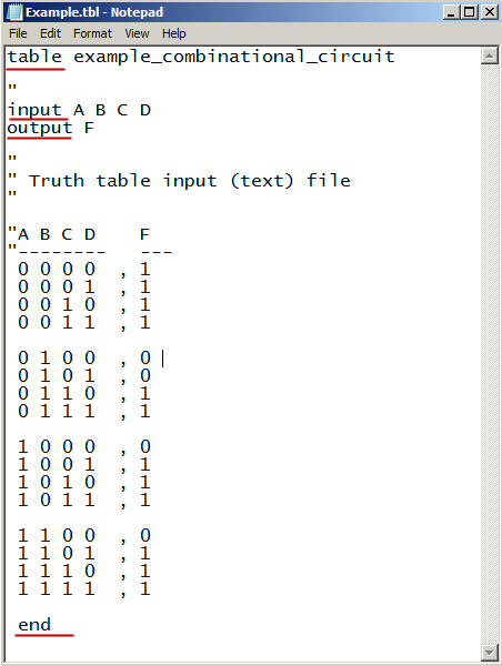 |
Fig. 3. Example truth table file ready for minilog. |
Copy the source file in your project folder, for instance: "L:\CSD\P1\minilog\" and run the application.
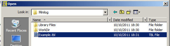 |
Fig. 4. |
Select the minimisation parameters and the type of resulting minimised equations. This time, in order to generate the circuit_Q, choose SoP.
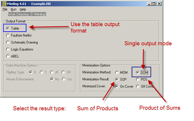 |
Fig. 5. Selection of the parameters. Single output mode (SOM) and output table format. (Do not use the logic equations format). |
Execute the minimise order.
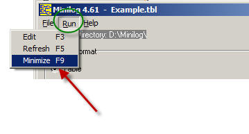 |
Fig. 6. Click F9 to start the process of minimisation. |
Inspect the resulting file showing the output table format: Example.min
 |
Fig. 7. Result in table format to be interpreted as an equation in the SoP form. |
The resulting equation in SoP from the table interpretation: F = A'·B' + A·D + C
Draw the Circuit_Q from this equation. To complete the project, now is time for checking that this equation produces the same truth table represented in Fig.1. You may use WolframAlpha or Proteus to perform this test.
3. An example circuit (PoS)
This is an example on the use of minilog to design a circuit based on simplyfied equations derived from the truth table. Fig. 1 shows the circuit's truth table. The aim of this problem is to invent another circuit, for instance Circuit_R, based on PoS. Thus, Fig. 2, Fig. 3 and Fig. 4 are the same. Click the option PoS as shown in Fig. 8.
 |
Fig. 8. Selecting the output in PoS. |
Inspect the resulting file showing the output table format: Example.min
 |
Fig. 9. The file example.min |
The resulting equation in PoS from the table interpretation: F = (A' + C + D) · (A + B' + C)
Draw the Circuit_R from this equation. To complete the project, now is time for checking that this equation produces the same truth table represented in Fig.1. You may use WolframAlpha or Proteus to perform this test.
Other similar tutorial exercises
Another complete example for minimising logic functions using Minilog (docx). Truth table example "HEX_7SEG_basic.tbl" The idea is always start with a file which already runs and modify it accordingly to the new problem truth table. Another truth table example which uses "don't care terms": "HEX_7SEG_all.tbl" .
| Home Term 26/27-Q1 Contact Products Electronic devices and companies Software Books Magazines Instruments DEE Library EETAC DEEL |

|
|
| Web activa des de 09/2001, @ F. J. Robert, Web editat amb Microsoft Expression Web 4. El contingut és un complement als materials d'estudi del curs Circuits i Sistemes Digitals disponibles al campus digital Atenea. Llicència:Reconeixement 4.0 Internacional de Creative Commons |