|
|
Bachelor's Degree in Telecommunications Systems and in Network Engineering |
|
|
Basic concepts on PWM peripheral |
||
Adjustable rectangular waveform generator
1. Architecture and configuration bits
The Microchip PWM is attached to the TMR2 peripheral.
- Firstly, study the TMR2.
- Search for the peripheral section in the microcontroller datasheet.
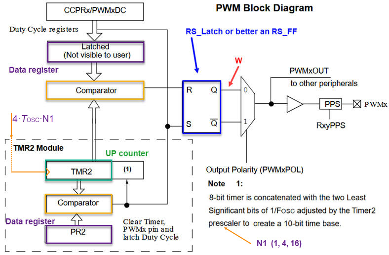
- Analyse the peripheral's schematic or block diagram in Fig. 1. Determine how does it work and how the output waveform is modulated.
- Determine its design equation on how to use it in our applications.
Discussion on the PIC PWM module architecture. The PWM module will be conceived as an adaptation of the PWM-TMR2 Microchip PIC18F diagram copied in Fig. 1. from the datasheet or from this technical brief reference: Barbulescu, G., Bujor, I., "TB3270: Getting Started with PWM Using CCP on PIC18", Microchip.
|
|
|
Fig. 1. The initial idea on generating PWM waveforms from the datasheet: the PWM module is associated with TMR2. The output wave is generated setting and resetting a simple RS latch cell. TMR2 comparator will drive S, establishing the waveform period (WP) determined by the value stored in PR2. Another comparator, by means of the duty cycle register will drive R configuring the pulse width (PW). |
|
|
|
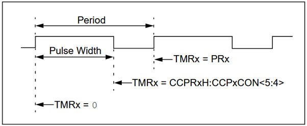
Fig 2. Waveform parameters as depicted in the datasheet. |
2. Example project: LED dimmer.
Visit the capstone dimmer project at DEE.
| Home Term 26/27-Q1 Contact Products Electronic devices and companies Software Books Magazines Instruments DEE Library EETAC DEEL |

|
|
| Web activa des de 09/2001, @ F. J. Robert, Web editat amb Microsoft Expression Web 4. El contingut és un complement als materials d'estudi del curs Circuits i Sistemes Digitals disponibles al campus digital Atenea. Llicència:Reconeixement 4.0 Internacional de Creative Commons |