|
|
Bachelor's Degree in Telecommunications Systems and in Network Engineering |
|
Chapter 3 problems |
- B3.13 - |
3-digit BCD subtractor (µC - C) |
1. Specifications
As a way to start using the new developing environment (IDE) and to discover the main details of microcontroller architecture and how to program it, we can try to solve in C for a target chip PIC18F46K22 several components belonging to the 8-bit subtractor proposed in D1.13 and reproduced in Fig. 1 along with its internal circuit in Fig. 2.
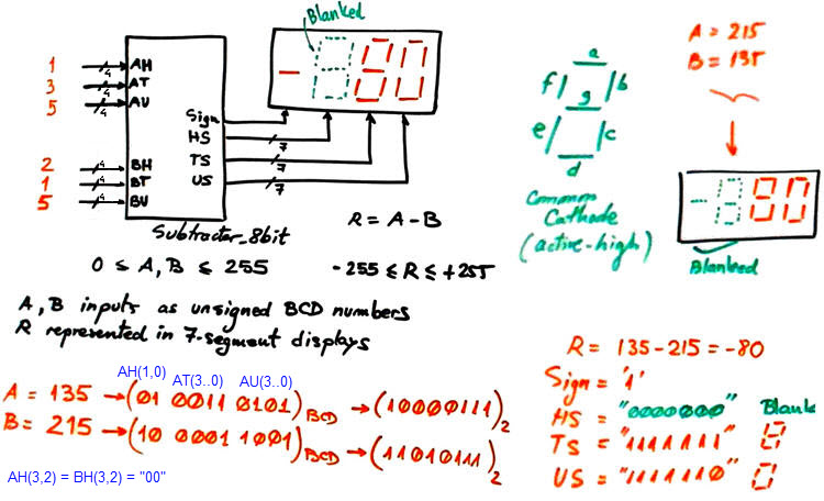 |
Fig. 1. The entity of a Subtractor_8bit and an example operation. |
|
|
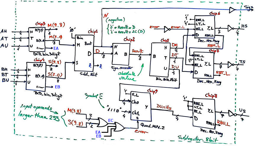
Fig. 2. Fully-annotated architecture for the full Subtractor_8bit ready for VHDL translation in D1.13. |
Project #1 Chip1 + Chip2: Subt_8bit + Sign_corrector. This combination may be named Subt_radix2_8bit as represented in Fig. 3.
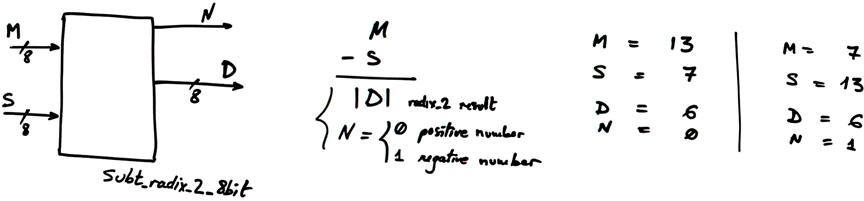 |
Fig. 3. Symbol of the Subt_radix2_8bit. |
Pin assignment option #1:
| M(7..4) ---> RA(5..2) | M(3..0) ---> RB(7..4) | |
| S(7..6) ---> RA(1..0) | S(5..2) ---> RB(3..0) | S(1..0) ---> RC(7..6) |
| D(7..2) ---> RC(5..0) | D(1..0) ---> RD(7..6) | |
| N ---> RE(2) |
Pin assignment option #2:
| M(7..5) ---> RD(5..3) | M(4..1) ---> RC(7..4) | M(0) ---> RA(0) |
| S(7..5) ---> RD(2..0) | S(4..0) ---> RB(7..3) | |
| D(7..5) ---> RE(3..1) | D(4..0) ---> RA(5..1) | |
| N ---> RD(7) |
Pin assignment option #3:
| M(7..4) ---> RC(5..2) | M(3..0) ---> RB(7..4) | |
| S(7..6) ---> RB(3..2) | S(5..0) ---> RA(5..0) | |
| D(7..6) ---> RC(1..0) | D(5..0) ---> RD(7..2) | |
| N ---> RD(0) |
Project #2 Chip3: BCD_bin_3digit [B3.15]. Pin options are given in this related assignment.
 |
Fig. 4. Symbol for the BCD_bin_3digit code converter. |
Project #3 Chip5: Bin_BCD_9bit [B3.16] (let us add another bit to the binary input). Pin options are given in this related assignment.
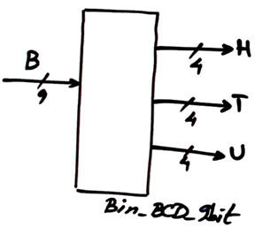 |
Fig. 5. Symbol for the Bin_BCD_9bit code converter. |
Project #4 Chip6 - Chip7 - Chip8: the three of them integrated in a single 3-digit multiplexed hexadecimal to 7-segments decoder. Similar tutorial on multiplexed display systems at MDS. Pin options and details are given in this related assignment [B3.7].
Microcontrollers do not have many pins, thus it is convenient to generate a multiplexed display system (MDS) to reduce the pin count when several displays are required in a given application, for instance this MDS_BCD_7seg_3digit.
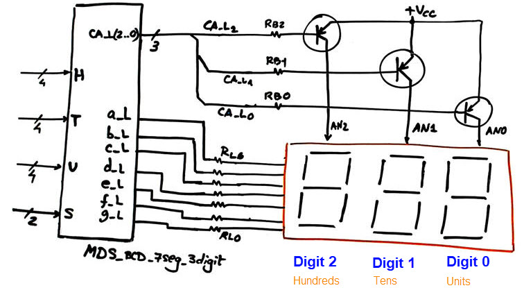 |
Fig. 6. Symbol for this MDS_HEX_7seg_3digit. |
| Home Term 26/27-Q1 Contact Products Electronic devices and companies Software Books Magazines Instruments DEE Library EETAC DEEL |

|
|
| Web activa des de 09/2001, @ F. J. Robert, Web editat amb Microsoft Expression Web 4. El contingut és un complement als materials d'estudi del curs Circuits i Sistemes Digitals disponibles al campus digital Atenea. Llicència:Reconeixement 4.0 Internacional de Creative Commons |