|
|
Bachelor's Degree in Telecommunications Systems and in Network Engineering |
|
Legacy hardware: Altera DE0 board |
| Prototype specifications | Planning | Development and Test & Measurements |
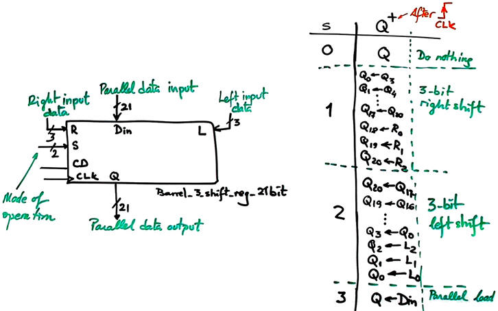
Let us adapt the Barrel_3_shift_reg_21bit represented in Fig. 1 for the Altera DE0 board populated with an obsolete target chip FPGA Cyclone III. This board is a classic that was used for many years in teaching and learning digital systems worldwide.
 |
|
Fig. 1. Symbol of the barrel shifter. |
We will add some additional features to the top design, such:
- Switch for selecting two CLK frequencies for fast (20 Hz) and slow (1 Hz) shifting (Sel_CLK_freq)
- Two switches for selecting the mode of operation.
This is the time for reviewing the DE0 board hardware.
-Basics of CPLD and FPGA.
- CPLD Cyclone III architecture. Number of logic elements available for experimentation.
- How to configure the FPGA device using a JTAG configuration (*.sof RAM file).
- How to configure the FPGA device using a JTAG configuration (*.pof EPROM file).
- Electronic schematic. Which board resources are easy to use for an introductory level project? User switches, LED, push-buttons, 7-segment displays, etc.
| Prototype specifications | Planning | Development and Test & Measurements |
We will follow the steps:
1. Develop and test functionally the application in Quartus Prime. Project folder:
C:\CSD\LEGACY\DE0\Barrel_3_shift_reg_21bit_top\(files)
2. Copy the project's VHDL source files in the Window 7 VM for resynthesising using Quartus II 9.0, an edition in which we still can use Cyclone III as target chip. Assign pins and generate the configuration files: *.sof,*.pof. Project folders in Windows 7:
C:\CSD\DE0\Barrel_3_shift_reg_21bit_top\(files)
3. Use the Programmer JTAG interface to configure the FPGA with the *.sof file. This configuration is volatile, when powering off and on the board the FPGA does not keep its configuration.
4. Use the JTAG interface to program the FPGA EPROM with the *.pof file. This configuration is non-volatile, when powering off and on the board the FPGA reads its configuration form the EPROM.
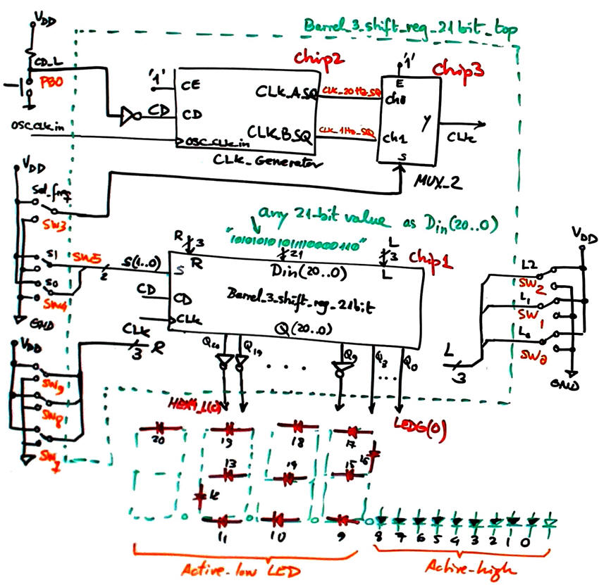
The following fully annotated plan C2 schematic is proposed for this adaptation to the FPGA board.
 |
|
Fig. 2. Barrel_3_shift_reg_21bit_top adaptation. |
| Prototype specifications | Planning | Development and Test & Measurements |
Developing will be integrated with testing for each of the planned steps. We can only go ahead when the current steps works correctly.
1. Quartus Prime project
To complete the synthesis and functional testing of our application, we can develop the project using our current Quartus Prime EDA. At this stage we can select any target FPGA.
The only circuit to which pay some attention is the CLK_Generator, to be adapted to the 50 MHz quartz crystal available in the DE0 board. let us generate squared CLK signals of 20 Hz and 1 Hz. The first frequency divider is N1 = 1250000. The second frequency divider is N2 = 20.
This is the list of VHDL files included in the Quartus Prime project "Barrel_3_shift_reg_21bit_top.zip".
 |
| Fig. 3. RTL Figure out the number of D_FF in use. |
The DE0 user manual indicates how to configure programmable devices and assign pins. Fig. 4 is elaborated from datasheet information.
 |
| Fig. 4. DE0 board layout indicating pin connections to LED, switches and 7-segment displays. |
2. Quartus II project. Pin assignment, configuration files
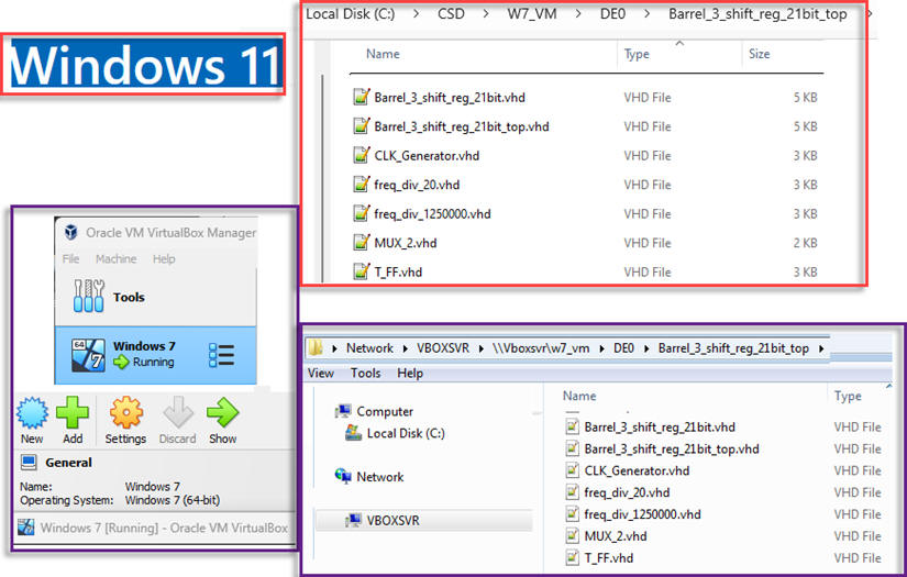
In this next stage, we can switch computers and tools to be able to target the obsolete Cyclone III device. Let us use the VM running Windows 7 and Quartus II version 9.0. Use the shared drive to copy the VHDL source files.
 |
|
Fig. 5. Shared folder C:\CSD\VM_W7 between Windows 11 and the Window 7 VM. |
Let us start a new VHDL project for the Cyclone FPGA including all the imported VHDL files. If we have to use the same environment for different legacy chips, it is convenient to organise the projects in separated folders. For instance:
C:\CSD\DE0\Barrel_3_shift_reg_21bit_top\(files)
This is the top project to be opened in Quartus II "Barrel_3_shift_reg_21bit_top.zip".
Once the project synthesised with no errors, we can use the pin planner tool to assign pins as shown in Fig. 6 and re-synthesise the project to obtain the output configuration file. In this way, the "Barrel_3_shift_reg_21bit_top.pof" will be ready for programming the CPLD in the next step.
 |
|
Fig. 6. Pin assignments can be saved in a file "Barrel_3_shift_reg_21bit_top.csv" ready to be imported to the Quartus II project. |
3. JTAG, *.sof
JTAG programming: In this method of programming, named after the IEEE standards Joint Test Action Group, the configuration bit stream is downloaded directly into the Cyclone III FPGA. The FPGA will retain this configuration as long as power is applied to the board; the configuration is lost when the power is turned off. Let us use the USB cable to download the configuration file for the FPGA SRAM indicated in Fig. 6.
 |
|
Fig. 6. Using the USB JTAG interface for configuring the SRAM with the "*.sof" file. |
Be aware of connecting the USB cable to detect the USB Blaster.
When ready, use the programmer tool installed in your Windows 11 computer to locate the target chip where to upload the configuration file. This is the "Barrel_3_shift_reg_21bit_top.sof" file
|
|
|
Fig. 7. Programmer application. It also works as an standard alone application. |
This FPGA configuration step can be executed directly from the Programmer as an standard-alone app. Let us use the "Barrel_3_shift_reg_21bit_top.sof" file for the FPGA produced above in Quartus II. The Cyclone III EP3C16F484C6N will be detected in the JTAG chain as shown in Fig. 8.
 |
|
Fig. 8. The Cyclone III 3C16F484C6N is detected as a programmable device attached to the JTAG chain. |
Check that the DE0 board works as expected running the "Barrel_3_shift_reg_21bit_top" configuration.
4. JTAG, *.sof
We can leave the application permanently installed in the boards' FPGA configuration EPROM. Change the programmer mode to "Active Serial Programming" to detect the board's serial EEPROM EPCS4. It provides non-volatile storage of the bit stream, so that the information is retained even when the power supply to the DE0 board is turned off. When the board's power is turned on, the configuration data in the EPCS4 device is automatically loaded into the Cyclone III FPGA.
This is the "Barrel_3_shift_reg_21bit_top.pof" file.
 |
|
Fig. 9. Configuring the EPROM with the output file *.pof. |
| Home Term 26/27-Q1 Contact Products Electronic devices and companies Software Books Magazines Instruments DEE Library EETAC DEEL |

|
|
| Web activa des de 09/2001, @ F. J. Robert, Web editat amb Microsoft Expression Web 4. El contingut és un complement als materials d'estudi del curs Circuits i Sistemes Digitals disponibles al campus digital Atenea. Llicència:Reconeixement 4.0 Internacional de Creative Commons |