|
|
Bachelor's Degree in Telecommunications Systems and in Network Engineering |
|
|
|
|||
|
|
1-digit BCD counter with LCD and TMR1 and A/D (design phase #4) |
|
|
|
|
|||
A/D example application
| 1. Specifications | Planning | Dev. & test | Prototype | report |
A way to introduce analogue to digital conversions, is to use an external potentiometer. The analogue input signal vA from the potentiometer AN0 available on the CSD_PICstick board is captured by the PIC18F46K22 10-bit analogue to digital (A/D) converter.
 |
| Fig. 1. Analogue to digital conversion. |
We can use the previous phase #3 timing periods TP = 1 s or TP = 8.33 ms as sampling periods TS. The push-button Sel_freq will select between fS = 1 Hz and fS = 12 Hz.
This time let us use the CSD_PICstick switch CE to select between representing analogue voltages or counting BCD values.
 |
| Fig. 2. Symbol and signals used in this design phase #4. |
| Specifications | 2. Planning | Dev. & test | Prototype | report |
A) Planning hardware
The only new connection from the previous design phase #3 is the AN0 analogue input at pin RA0.
B) Planning software
We need to synchronise analogue to digital conversion on TMR1 interrupts as the way to fix the sampling frequency at the same var_CLK_flag. In this simple application, most of the A/D parameters will be fixed in init_system(). The function analogue_read() will start conversions and wait for end of conversion in a few microseconds (conversion time TC = 11·TAD).
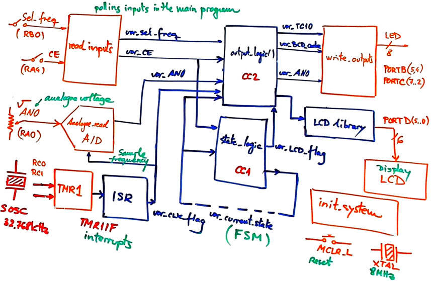 |
| Fig. 3. Hardware-software diagram. |
Organise an MPLABX - XC8 IDE project targeting a PIC18F46K22 at location:
C:\CSD\P12\c_BCD_1d_LCD_TMR1_AD\(files)
| Specifications | Planning | 3. Dev. & 4. test | Prototype | report |
A) Developing hardware
This is the circuit in Proteus: "Counter_BCD_1digit_LCD_TMR1_AD.pdsprj".
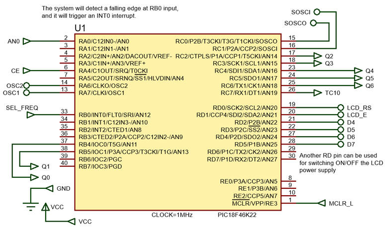 |
| Fig. 4. µC connections. |
B) Developing software
The XC8 compiler version is v3.0 or newer, C standard is C99. And these LCD library files "lcd.c", "lcd.h" have to be included in the project. The file "config.h" contains all the microcontroller configuration bits.
This is the source file: "Counter_BCD_1digit_LCD_TMR1_AD.c".
C) Step-by-step testing
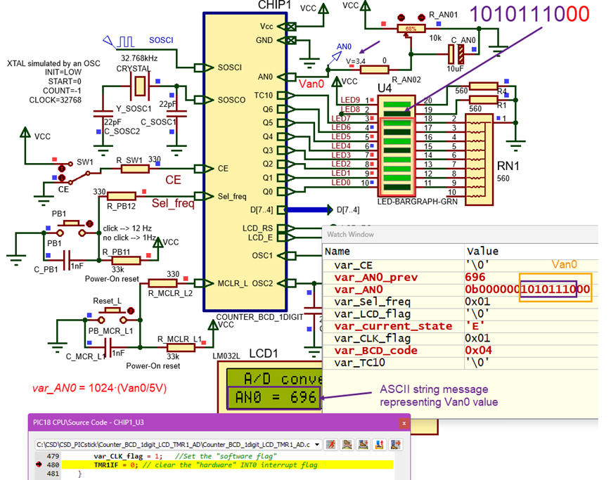 |
| Fig. 4. Counter_BCD_1digit_LCD_TMR1_AD captured in Proteus showing RAM variable is the watch window and all the mC pins in use. |
| Specifications | Planning | Dev. & Test | 5. Prototype | Report |
We have adapted the hardware so that we can mount the application using the PCD_PICstick.
| Specifications | Planning | Dev. & Test | Prototype | 6. Report |
Follow this rubric for writing reports.
| Home Term 26/27-Q1 Contact Products Electronic devices and companies Software Books Magazines Instruments DEE Library EETAC DEEL |

|
|
| Web activa des de 09/2001, @ F. J. Robert, Web editat amb Microsoft Expression Web 4. El contingut és un complement als materials d'estudi del curs Circuits i Sistemes Digitals disponibles al campus digital Atenea. Llicència:Reconeixement 4.0 Internacional de Creative Commons |