|
|
Bachelor's Degree in Telecommunications Systems and in Network Engineering |
|
|
Acquiring analogue signals: FSM, A/D, LED bar, MCC |
| 1. Specifications | Planning | Dev. & test | Prototype | Report |
Let us program a basic application using MCC Melody hardware configuration functions. It will be a professional alternative programming style to access, configure and control all the microcontroller hardware resources.
- ST/SP button ST_L to start and stop operations.
- Timing peripheral used as the sampling CLK.
- Use a switch SF to select 10 Hz or 1 kHz sampling frequencies.
- Write the 10-bit captured digital value Q(9..0) in a LED bar.
- Output signal (toggle value) every sampling period TS. The sampling frequency fS is generated using any of the timers available, which will be liberated when not in use in Idle state.
- Pinning adapted to the CSD_PICstick board.
- FSM style to control the program flow.
|
|
|
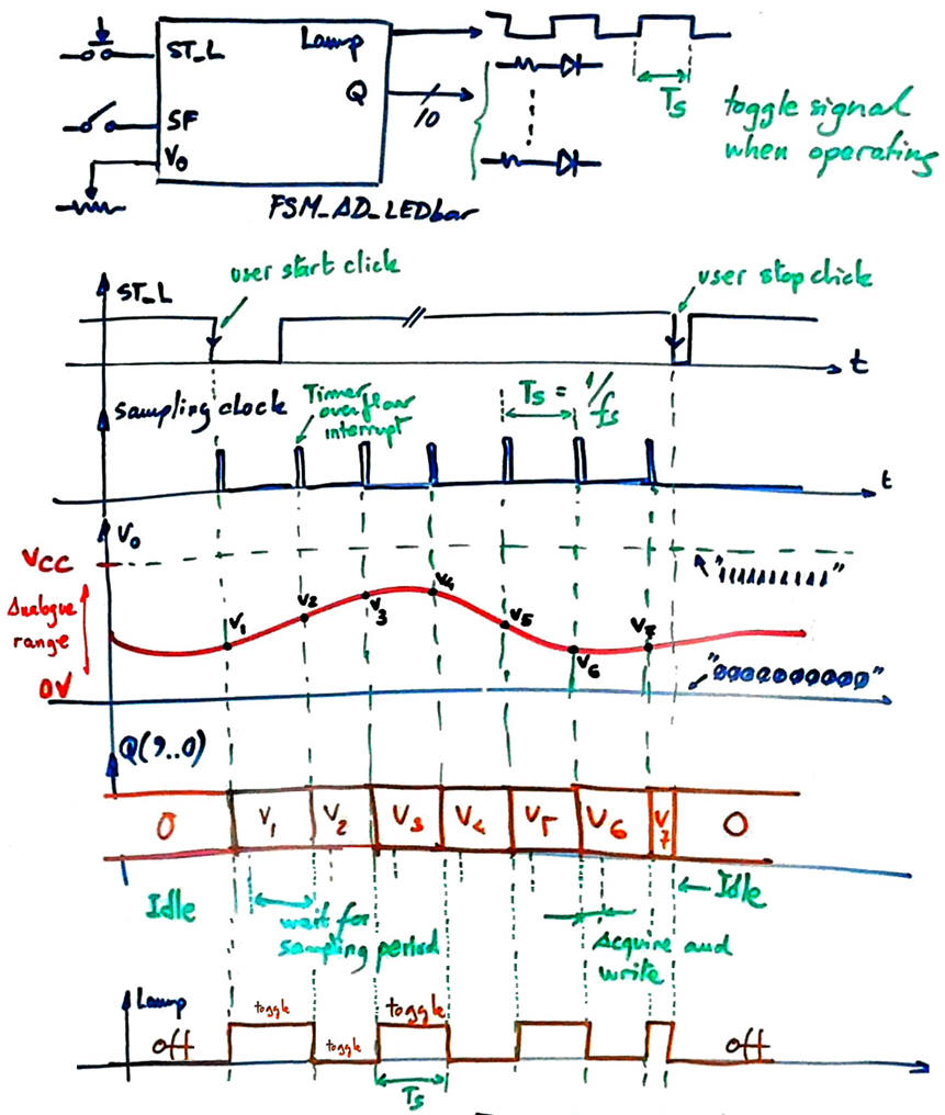
Fig 1. Symbol and waveforms. For most of the period, the µC is doing nothing, but waiting for another sampling clock overflow to take the next A/D sample. |
| Specifications | 2. Planning | Dev. & test | Prototype | Report |
A) Planning hardware
We simply will adapt pinning to the CSD_PICstick platform. We will run MCC to generate all the required functions to control hardware resources as it were another tutorial ass shown in Fig.2.
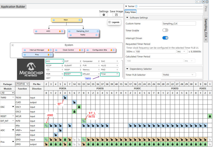 |
Fig 2. Hardware resources selected from the Melody code configurator. |
The electronic circuit is represented in Fig. 3.
|
|
|
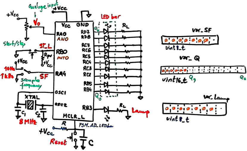
Fig 3. Electronic circuit: external crystal oscillator, 10 LED bar for Q(9..0), Lamp LED to indicate the sampling period TS, a potentiometer to input the V0 analogue voltage in the A/D range VREF+ > V0 ≥ VREF-, a switch SF to select between two sampling frequencies, and the ST_L start/stop push-button. |
B) Planning software
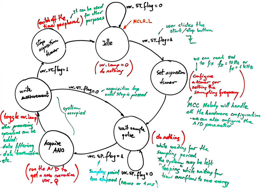
As shown in the state diagram, the FSM will control this application. We have selected a peripheral timer (TMR0) to generate overflow interrupts every TS = 100 ms or TS = 1 ms, depending on the value SF read.
|
|
|
Fig 2. FSM state diagram. The timer will be in service only when acquiring. In this way it is easy to add new functionalities and reuse peripherals. The key state is wait_sampling_pulse, the µC is doing nothing until the next sampling period. Therefore, it can be put in sleep mode to save energy. |
Project location:
C:\DEE\LAB6\PIC18F\FSM_AD_LEDbar
| Specifications | Planning | 3. Dev. & 4. test | Prototype | Report |
A) Developing hardware
We can use some elements of the CSD_PICstick board modelled in Proteus as the hardware platform where to check our circuit.
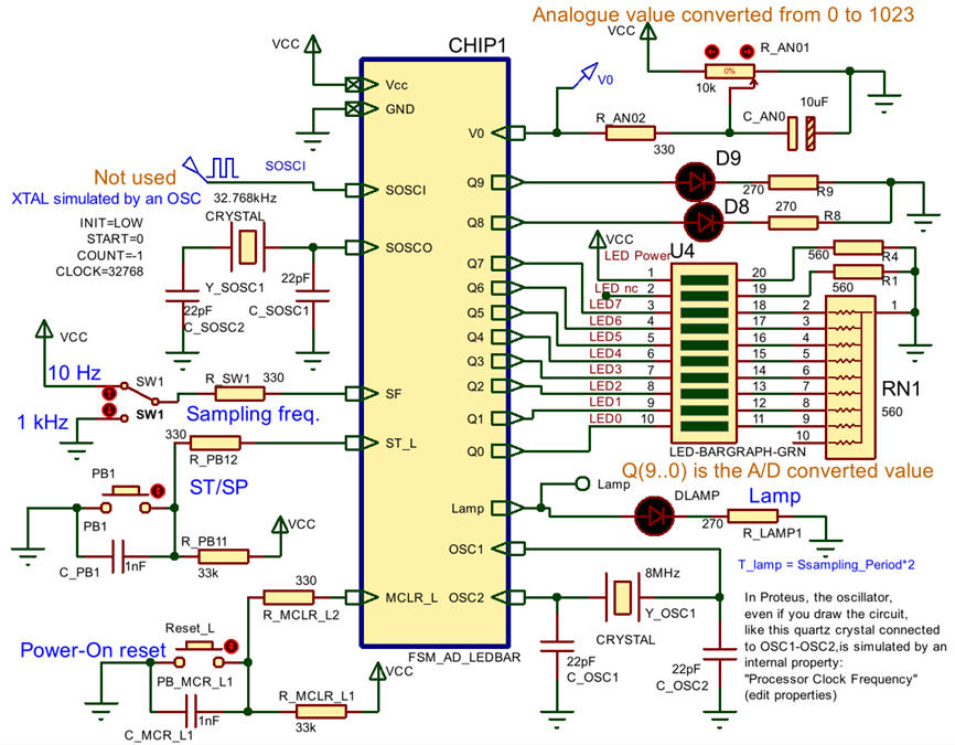 |
Fig 4. Circuit captured in Proteus modelling the CSD_PICstick board resources. We will add three additional LED through the expansion connector. |
B) Developing software
We can adapt this application from a previous tutorial such Blink_LED_FSM.
The full project "FSM_AD_LEDbar.zip". Start a project using MPLAB v6.30 or newer and XC8 v3.10 or newer. The MCC generated header file "tmr0.h" contains a #define list that makes transparent the specific TMRx module selected for this application. Thus, changing this module, means that we do not have to rewrite a single line of C code.
Use Proteus 9.1 or newer to simulate the application or download the programming file to the CSD_PICstick using MPLAB SNAP.
C) Step-by-step testing
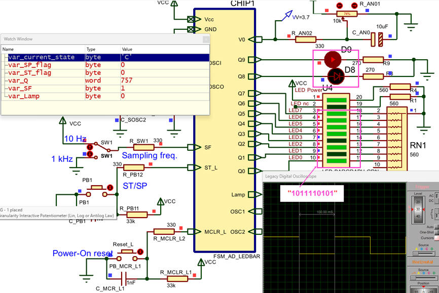 |
Fig 4. Checking the application using Proteus debugging resources. |
| Specifications | Planning | Dev. & Test | 5. Prototype | Report |
Let us downloaded the program to the microcontroller and experiment with the board. If necessary we can run the MPLAB SNAP in-circuit debugger.
Fig 5. Circuit operating on the CSD_PICstick board. |
| Specifications | Planning | Dev. & Test | Prototype | 6. Report |
| Home Term 26/27-Q1 Contact Products Electronic devices and companies Software Books Magazines Instruments DEE Library EETAC DEEL |

|
|
| Web activa des de 09/2001, @ F. J. Robert, Web editat amb Microsoft Expression Web 4. El contingut és un complement als materials d'estudi del curs Circuits i Sistemes Digitals disponibles al campus digital Atenea. Llicència:Reconeixement 4.0 Internacional de Creative Commons |