|
|
Bachelor's Degree in Telecommunications Systems and in Network Engineering |
|
| Laboratory |
Laboratory 1.0: designing and soldering a logic probe. Prototyping electronic circuits |
[10 Sep] |
1.1.3. Laboratory prototypes
This preliminary laboratory activity is for learning to solder electronic components using basic tools. There are many books and web pages that can teach you this important skill for prototyping electronic projects.
|
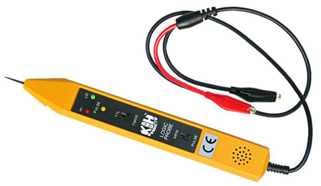
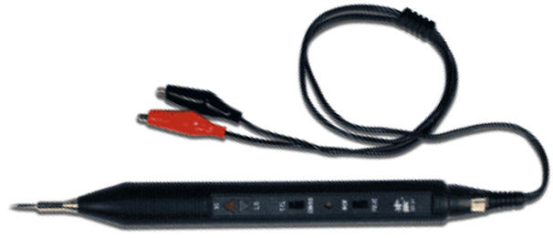
Project tutorial: Designing a logic probe, a simple instrument |
Let us conceive a simple instrument: a logic probe, to visualise logic values and detect digital signals. It will be a kind of bridge circuit between ET (1A), CSL (1B) and CSD (2A) where analogue comparators will detect digital voltage thresholds and fast signal transitions.
  |
|
Fig. 1. Example of a commercial logic probes from these references 1, 2, 3, 4, 5. |
| Home Term 26/27-Q1 Contact Products Electronic devices and companies Software Books Magazines Instruments DEE Library EETAC DEEL |

|
|
| Web activa des de 09/2001, @ F. J. Robert, Web editat amb Microsoft Expression Web 4. El contingut és un complement als materials d'estudi del curs Circuits i Sistemes Digitals disponibles al campus digital Atenea. Llicència:Reconeixement 4.0 Internacional de Creative Commons |