|
|
Bachelor's Degree in Telecommunications Systems and in Network Engineering |
|
|
Laboratory 1_1: analysis of simple circuits based on logic gates. Method II - Method IV This is the highlighted reference Circuit_C [P1] for practising with analysis methods |
[19/9] |
|
This is the individual post lab assignment PLA1_1 to be submitted next Lab1_2 session. Study in detail and execute in your computer this lab tutorial and the reference design before attempting to solve the PLA. |
1.4.2. Analysis method II: Proteus simulation (virtual laboratory) for truth tables and deducing logic circuits
1.4.2.1. SPICE algorithms
1.4.2.1.1. Proteus ISIS from Labcenter Electronics (EETAC cloud licence available)
| 1. Specifications | Planning | Developing | Testing | Report |
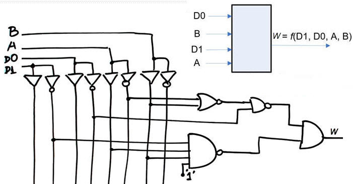
Our goal is to deduce Circuit_W truth table W = f (D1, D0, A, B) by means of running Proteus simulations (method II). This is a tutorial and a video rec. on how to proceed with Proteus to deduce a circuit truth table. Circuit's components can be from TTL-LS or CMOS libraries, but do not mix components from different libraries in the same schematic.
|
|
|
Fig. 1. Symbol and internal architecture of Circuit_W. |
| Specifications | 2. Planning | Developing | Testing | Report |
Draw a plan for this analysis method II. It is possible to model logic gates using CMOS or TTL-LS libraries. Draw all gates using the same library.
|
|
|
Fig. 2. This sketch explains the plan to follow to deduce the Circuit_W truth table. You must add/modify/delete the circuit step by step (one gate at a time) and run to check that it works correctly. |

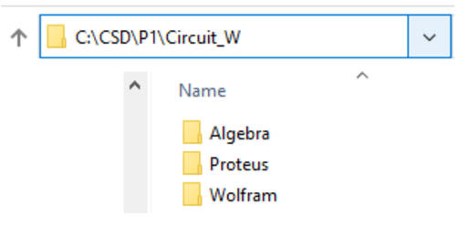
This is the project location:
C:\CSD\P1\Circuit_W\Proteus\(Circuit_W.pdsprj and other files)
| Specifications | Planning | 3. Developing | Testing | Report |
Use a mouse with your portable computer to make it easier to draw the circuit and navigating through the many tabs.
Find a similar circuit to copy and adapt from this DIGSYS web. Change its name and save it in the given directory.
In this tutorial we will use either TTL-LS (74LS) or CMOS series 4000B libraries of classic components. For instance: a 3-input NOR gate in classic CMOS 4000 technology is the 4025B; the same 3-input NOR in TTL-LS technology is 74LS27. Do not mix gates from different logic families, they may not be electrically compatible.
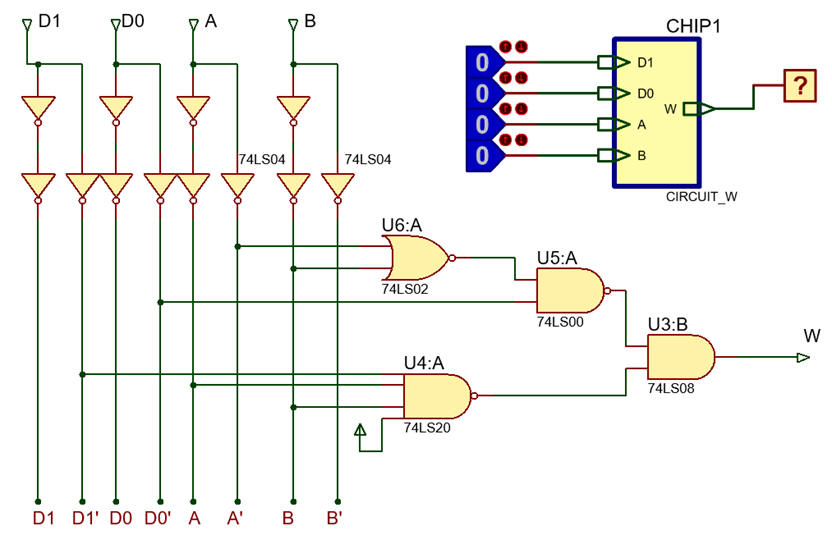
This is an example Circuit_W.pdsprj capture using LS-TTL (VCC = 5 V, VGND = 0 V). Print the captured circuit to demonstrate that you are able to draw circuits as shown in Fig. 3. This is the same Circuit_W.pdsprj capture using CMOS (VDD = 15 V, VSS = 0 V).
|
|
|
Fig. 3. Example of picture showing how the Circuit_W is captured in Proteus tool. |
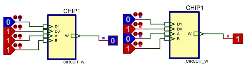
Run simulations applying all the binary combinations in order to complete your truth table.
|
|
|
Fig. 4. Simulation results when applying input binary combinations "0111" and "0101". We can observe that "0111" generates the maxterm M7 and "0101" generates the minterm m5. |
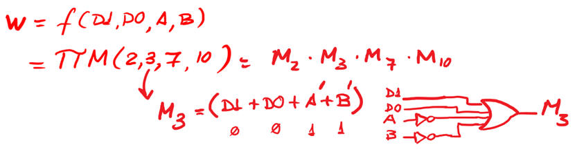
Write down your solution as a truth table or its equivalent canonical equations sum of minterms or product of maxterms.
|
|
|
Fig. 5. Problem solution using the canonical form of product of maxterms. |
| Specifications | Planning | Developing | 4. Testing | Report |
In CSD verifying your solutions means self-assessing your results. This is why comparing results from other methods is the best idea. For instance method I solved in class L1.3 or method IV to be solved in the project below.
In this way, this verification section (a sheet of paper) has to say something as simple as:
"My Circuit_W analysed using method II (Proteus) generates the same truth table that was obtained using method I".
| Specifications | Planning | Developing | Testing | 5. Report |
Follow this rubric for writing reports. This is an example that shows how to write a report of a circuit analysis using the method II based on Proteus simulations.
1.4.2.2. (Optional) digital simulators
1.4.2.2.1. HADES: interactive simulation framework based on JAVA applets (Univ. of Hamburg) (not covered).
1.4.2.2.2. DEEDS: digital electronics education and design suite (Univ. of Genoa) (not covered). This site promoted by prof. G. Donzellini is spectacular, recommended for learning digital circuits.
1.4.2.2.3. LogicWorks: is a schematic drawing and interactive digital simulation package for demonstrating logic design principles and practices within the education sector and industry.
|
Laboratory 1_1: Analysis of simple circuits based on logic gates. Method II - Method IV This is the highlighted reference Circuit_C [P1] for practising with analysis methods |
[19/9] |
|
Individual post lab assignment PLA1_1 to be discussed next Lab1_2. Solve and study all the details of this lab class before attempting to apply it to solve post lab assignment. |
1.4.4. Analysis method IV: WolframAlpha numerical engine for calculating truth tables and deducing logic circuits.
| 1. Specifications | Planning | Developing | Testing | Report |
Our goal is to deduce Circuit_W truth table W = f (D1, D0, A, B) using WolframAlpha numerical engine (method IV). Video rec. on how to proceed with WolframAlpha.
|
|
|
Fig. 1. Symbol and internal architecture of Circuit_W. |
| Specifications | 2. Planning | Developing | Testing | Report |
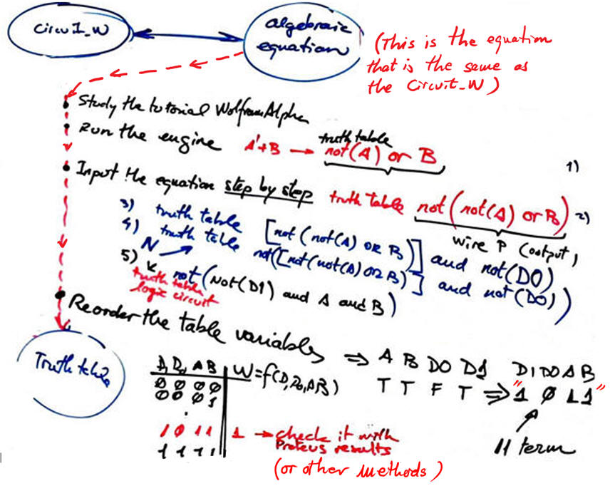
Draw a plan, a flowchart, a bullet list, for obtaining and checking your solution. For this method, the key point is to input the circuit equation step by step while running the engine to check that there are no errors when interpreting the equation.
|
|
|
Fig. 2. Proposed method IV detailed flowchart to carry out this analysis project. |
This is a convenient location for this project:
C:\CSD\P1\Circuit_W\Wolfram\(files)
Files may include your written equations Circuit_W_equ.txt and other files like printed result images.
| Specifications | Planning | 3. Developing | Testing | Report |
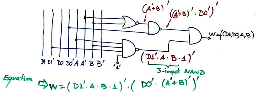
Analyse the circuit and obtain its logic equation, as shown in Fig. 3.
|
|
|
Fig. 3. Analysis gate by gate in order to find the equivalent circuit algebraic equation. |
Start writing simpler equations in a text file and try them in WolframAlpha. This file Circuit_W_equ.txt contains some equations to copy and paste into WolframAlpha. We use Notepad++ as enriched text editor for writing text equations.
Run WolframAlpha engine to get results: "truth table", "logic circuit".
Print WolframAlpha truth table and logic circuit in a sheet of paper.
|
|
|
Fig. 4. Example of printed and interpreted results from WolframAlpha. |
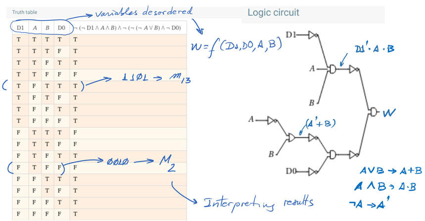
Reorder columns W = f (D1, D0, A, B) and complete the circuit's truth table identifying all minterms and maxterms.
|
|
|
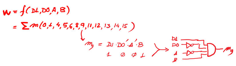
Fig. 5. Problem solution, the Circuit_W truth table, presented using the canonical form sum of minterms. |
| Specifications | Planning | Developing | 4. Testing | Report |
Compare results with other methods. For instance method I solved in class L1.3 or method II solved in the project above.
In this way, this sections has to say something as simple as
"My Circuit_W generates the same truth table when solved using method IV and method II".
| Specifications | Planning | Developing | Testing | 5. Report |
Follow this rubric for writing reports.
Summary of the complete discussions on Circuit_W analysis:
| 1. Specifications | 2. Planning | 3. Development | 4. Test |
| Find Circuit_W truth table | Method I | Handwritten analysis (L1.3) | Verify whether you are obtaining the same truth table for all methods. |
| Method II | Proteus tool | ||
| Method III | VHDL EDA tools and VHDL testbech simulation (next Lab1_2) | ||
| Method IV | WolframAlpha tool |
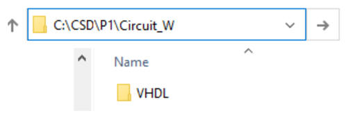
Furthermore, because most of the analysis and designs will require computer tools and applications, a folder is required for storing files from each project in your hard drive.
In next Lab1_2 we will study the same Circuit_W yet again with another analysis method:
| Home Term 24/25-Q1 Contact Products Electronic devices and companies Software Books Magazines Instruments DEE Library EETAC DEEL |

|
|
| Web activa des de 09/2001, @ F. J. Robert, J. Jordana. Web editat amb Microsoft Expression Web 4. El contingut és un complement als materials d'estudi del curs Circuits i Sistemes Digitals disponibles al campus digital Atenea. Llicència:Reconeixement 4.0 Internacional de Creative Commons |