|
L1.3: Circuit analysis using Boole's algebra (method I) P1 analysis. Example Circuit_W (a section of Circuit_C) |
[12/9] |
1.4. Analysis concept map: several methods for analysing simple combinational circuits
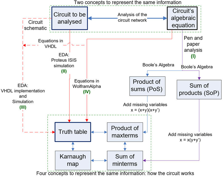 |
| Fig. 1. Analysisi map proposing several methods to deduce the circuit's truth table. |
1.4.1. Method I: Pen & paper analysis using boolean algebra
1.4.3.1. Properties of boolean functions
1.4.3.2. Duality principle, De Morgan's laws
1.4.3.3. Product of sums (PoS)
1.4.3.4. Sum of products (SoP)
1.4.3.5. Any type of equation or non-standard forms
1.4.2. Method II: Proteus simulation for truth tables and deducing logic circuits (Lab1_1)
1.4.4. Method IV: WolframAlpha engine for calculating truth tables and deducing logic circuits (Lab1_1)
To continue with the example circuit, to solve step 2, it is better to conceive it as a project:
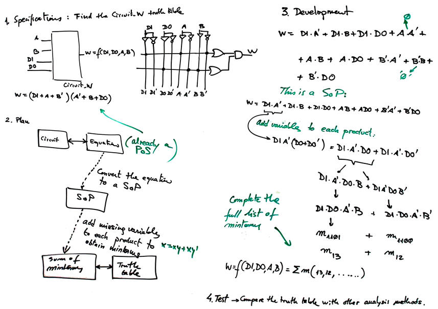
Specifications: Analyse a section of Circuit_C proposed in P1 to be named Circuit_W represented in Fig.2. Find its truth table using method I. This is a rec. on the idea of circuit analysis.
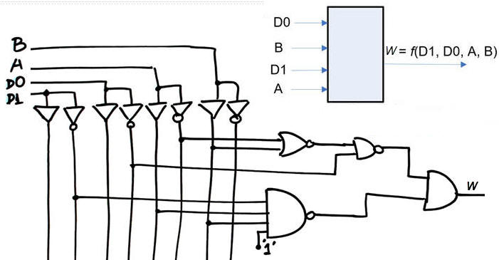 |
| Fig. 2. Circuit_W symbol and internal architecture. |
Planning: follow our concept map in Fig. 3:
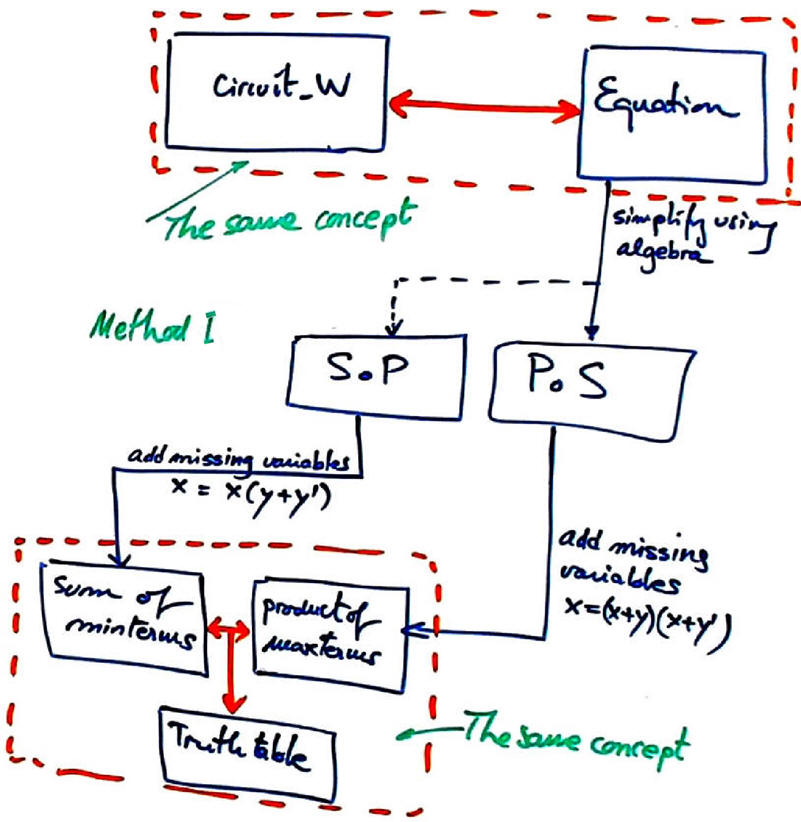 |
| Fig. 3. Plan for the analysis method I. |
-
Firstly, we deduce the circuit's equation: the logic diagram translated to an algebraic equation.
-
Secondly, applying algebra we simplify the circuit equation to obtain PoS.
-
Thirdly, we add missing variables to convert sums into maxterms using the identity x = (x+y)·(x+y'), and the product of maxterms is already the solution.
This is the folder where to save your notes, pictures, scanned diagrams and discussion:
C:\CSD\P1\Circuit_W\algebra\(files)
Development: This is Circuit_W solution rec. using the proposed analysis method I.
The initial concepts of circuit and its translation to an equation:
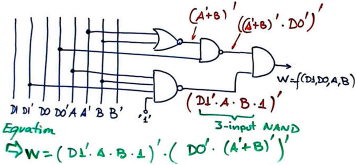 |
| Fig. 4. The Circuit_W equivalent equation. |
Now, we can begin the process of simplification using Boole's algebra as follows:
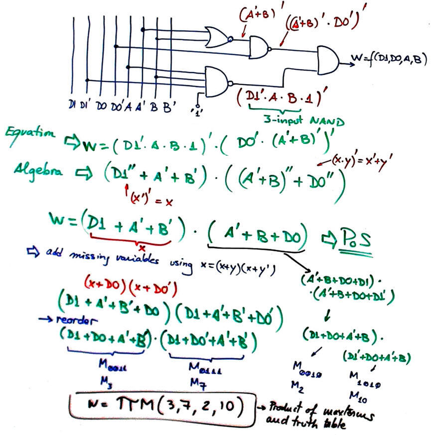 |
| Fig. 5. Simplifying using Boole's algebra to obtain a PoS equation or circuit. |
From the PoS expression in Fig. 5, we can continue converting the sums into maxterms adding in each term the the missing variables and reordering the inputs:
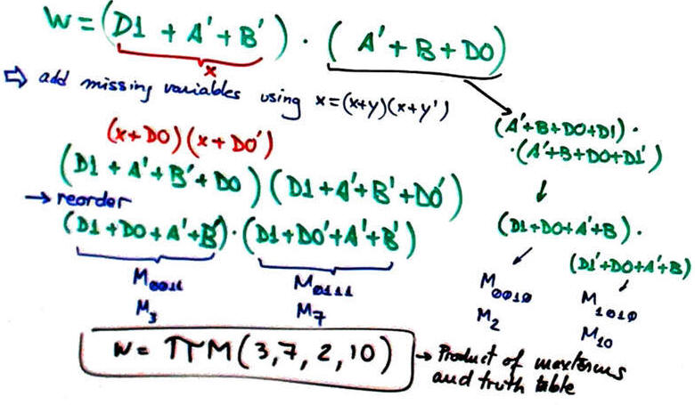 |
| Fig. 5. The final truth table deduced as a product of maxterms. |
Alternatively, from the circuit equation we obtain a SoP that becomes the sum of minterms adding missing variables in each product using x = x·(y + y') = x·y + x·y'.
Testing: This time, testing the validity of the truth table will be simply comparing solutions from other methods.
To complete step 3, repeat and apply all these concepts to Circuit_C proposed in P1
1.4.3. Method III: Analysis using synthesis and simulation EDA tools (Lab1_2)
Exercise: From the PoS simplifed expression obtained above

develop the equivalent SoP and convert each product into minterms. Check the final truth table.
These notes are an indication on how to organise this analysis project in our CSD style:
