|
|
Bachelor's Degree in Telecommunications Systems and in Network Engineering |
|
|
Installing and using Proteus-ISIS |
||
Computer simulation (virtual electronics laboratory) based on SPICE algorithms
1. Installation
Proteus is a virtual laboratory, a SPICE based electrical simulator. Its advantage for our course is that you can simulate both analogue and digital circuits based on classic components and also microcontrollers (Chapter 3 from P9).
You as EETAC student have to download and install the current professional version in your home or portable computer and run our cloud licence.
|
|
Fig. 1. Software logo. |
2. Example of a simple "flat" circuit
Capture a logic circuit in a Proteus project, and run simulations with the aim of obtaining its truth table. This is a simple flat capture, plan A, all the design at the same sheet of paper: circuit Comb_circuit.pdsprj in LS-TTL technology. It can be copied and adapted for other similar projects. This is the same Comb_circuit.pdsprj in CMOS technology.
NOTE: For your CSD assignments never start a new simulation project from scratch but copy & adapt from the many examples available in digsys.
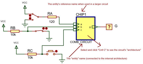 |
Fig. 2. A simple circuit that you can use as a template to be adapted to your design. This is a tutorial form the company Labcenter. |
This is another LS-TTL circuit Circuit_W.pdsprj adapted from above examples. This is an ideal version Circuit_W.pdsprj with generic gates and logic levels which is better not to use.
3. Scripting language Easy HDL
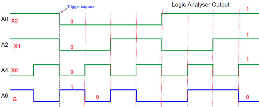
Sometimes it is a good idea to automate the generation of stimulus signals. The example Comb_circuit.pdsprj in Fig. 3 shows you how to use the internal scripting language Easy HDL for implementing digital generators, in this case a bus of three inputs. Firstly draw in paper your stimulus signals. Pay attention to the different parameters, wire label, scrip name, pins, loop variables, etc. You can also use the logic analyser instrument to observe the truth table in time. This is another example with Comb_circuit_three_inputs.pdsprj. This is another circuit with Comb_circuit_two_scripts.pdsprj.
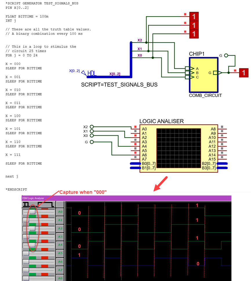 |
Fig. 3. Digital generator implemented using the Easy HDL scripting language and signal visualisation in the logic analyser. Important NOTE: when printing for written reports, never use black background, use write background to save printer ink as shown below:
|
4. Pattern generator instrument for providing stimulus digital signals
Fig. 4 represents yet another way to visualise the circuit truth table stimulating the circuit using a pattern generator instrument. In this simple case we are sending the eight values of the truth table G = f( C, B, A) repeatedly every second to the circuit. Circuit file: Comb_cir_pattern_gen.pdsprj, Pattern file: truth_table_pattern_gen.PTN.
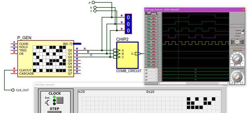 |
| Fig. 4. Using the pattern generator to stimulate a circuit with digital signals. |
4. Interfacing different types of real components
The circuit in Fig. 5 is another version Circuit_W_real.pdsprj where you can add to the digital electronic circuit Chip1 some buttons, switches, LEDs and even relays and motors. Play with the circuit and pay attention to the real voltages and currents that represent '0' and '1' symbolic logic values.
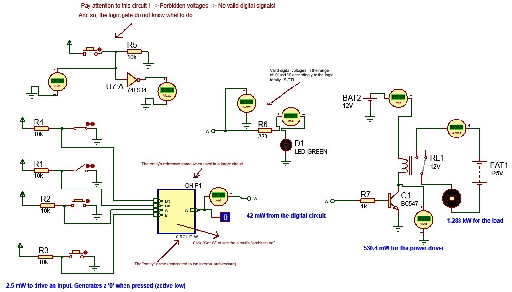 |
Fig. 5. Another digital circuit including real components (click the picture to zoom) to interface buttons and power loads. |
In Fig. 6, there is the detail of a power driver based on a simple bipolar junction transistor (BJT) and an electomechanical relay.
 |
Fig. 6. Logic gates manage uW of power, but conveniently amplified, can easily drive electric loads. In this example a kW motor is switch ON and OFF. |
5. Example of a hierarchical design using components (subcircuits)
Adder_subtractor_8bit.pdsprj occupies multiple structured hierarchical sheets of paper (plan C2). Such top-down circuit organisation that will allow us to draw large circuits will be studied from P3 sketching schematics and translating them to VHDL.
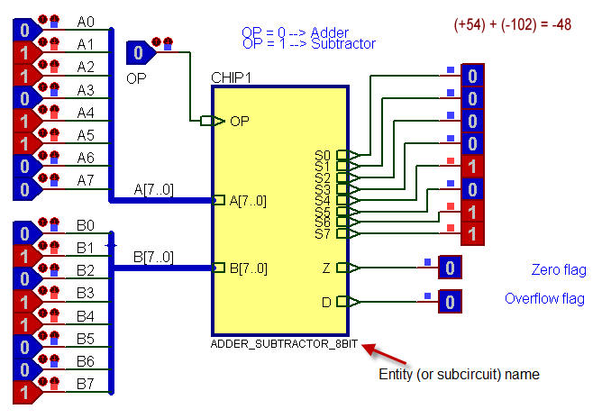 |
Fig. 7. The subcircuit block allows packing circuits in boxes or "entities" that can be used many times in the same schematic. This example can be taken as a hierarchical template circuit to copy and adapt. |
6. Other similar simulation tools and materials of interest
Multisim - Ultiboard (Emerson - NI)
This is the same project Circuit_W solved with another very powerful and full-featured SPICE simulator: MultiSim from National Instruments. As a UPC student you can download the software bundle Multisim (simulator) and Ultiboard (PCB design) for education and obtain a licence. These are instructions if you are interested in such EDA tools for other EETAC subjects.
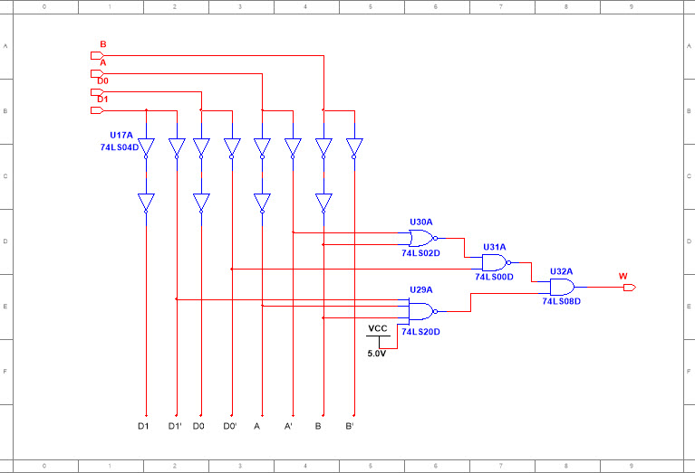 |
Fig. 8. Multisim circuit example. |
We can capture and run the basic functionality of the Arduino board in the Proteus VSM simulator. This is an Example_Arduino.pdsprj sample project including the simulation of the Arduino programm code. It generates a programmable PWM waveform.
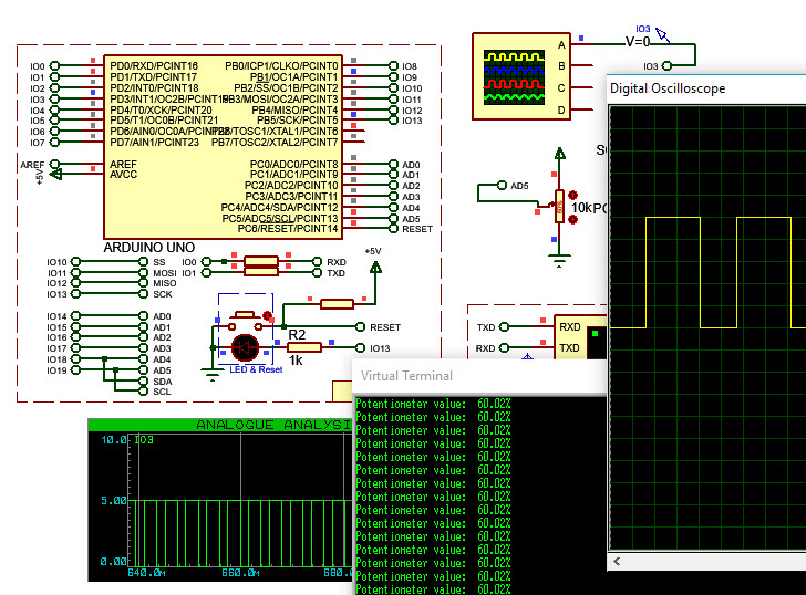 |
Fig. 9. Example of a circuit based on Arduino running in Proteus. |
| Home Term 24/25-Q1 Contact Products Electronic devices and companies Software Books Magazines Instruments DEE Library EETAC DEEL |

|
|
| Web activa des de 09/2001, @ F. J. Robert, J. Jordana. Web editat amb Microsoft Expression Web 4. El contingut és un complement als materials d'estudi del curs Circuits i Sistemes Digitals disponibles al campus digital Atenea. Llicència:Reconeixement 4.0 Internacional de Creative Commons |