|
|
|||||
Chapter 1 problems |
- D1.19 - |
31-slot parking occupancy system |
|||
|
|
|||||
1. Specifications
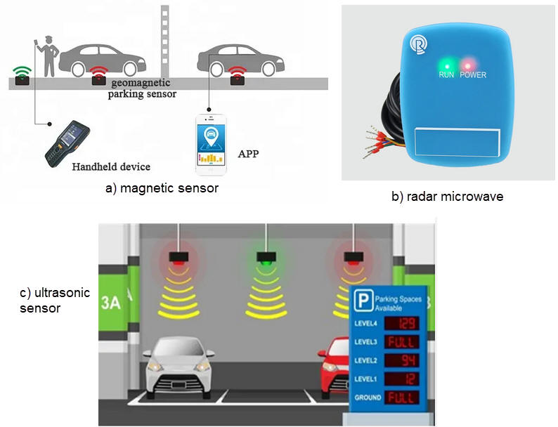
This project aims to represent in 7-segment displays the number of free parking slots in a 31 spaces parking garage. To detect cars several sensor technologies are available as pictured in Fig. 1: magnetic, microwaves, laser, ultrasonic, etc. We will assume that each slot has installed a sensor that generates a '1' when occupied. and '0' when free.
The same project B3.19 is proposed in Chapter 3 for learning the basics of μC software organisation and basic digital I/O.

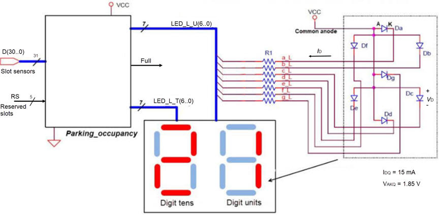
The symbol of the circuit is represented in Fig. 2.
 |
| Fig. 2. Symbol for the Parking_occupancy monitor to calculate the number of free parking slots avaialble for customers. |
Specifications include: symbol, truth table, data range, example timing diagram, etc. Invent the internal architecture of the Parking_occupancy circuit based on plan C2.
Draw an example of timing diagram to be used later as stimulus in the VHDL testbench when verifying the synthesised circuit. Consider Min_Pulse = 10.76 ms. Example of test options for checking the project, try at least these numbers:
option #1: Number of ones in D: 6, 18, 25, 31, 0, 12, 28; reserved slots RS: 5, 16, 2
option #2: Number of ones in D: 8, 16, 20, 31, 0, 3, 29; reserved slots RS: 15, 6, 1
option #3: Number of ones in D: 1, 7, 15, 30, 10, 0, 18; reserved slots RS: 10, 19, 3
2. Planning
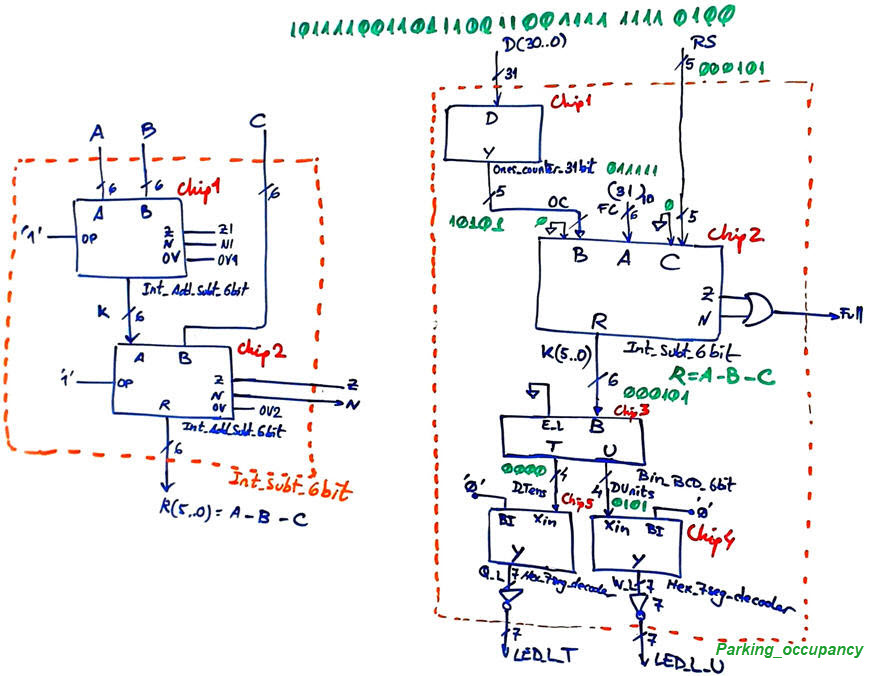
Thus, the first idea for planning the entity Parking_occupancy shown in Fig. 2 is to consider components such as Ones_counter_31bit where for example an input vector such as D = "100 1011 1110 1111 1000 1111 1010 1110" will produce an output occupied slots OS = (10101)2 = (21)10.
An arithmetic circuit can calculate the number of free slots (FS) subtracting from the full capacity (FC = 31) the number of reserved slots (RS) and the occupied spaces (OS): FS = FC - OS - RS. When FS = 0 or negative the flag Full will be used to block the parking entrance barrier.
A Bin_BCD_6bit converter can be used to drive the displays. For example an input such as K = (001101)2 will generate an output DTens = "0001", DUnits = "0011".
The HEX_7seg_decoder has active-low outputs to drive a common-anode display. Calculate the value of the limiting resistor R1 in the worst-case scenario if each segment must be biased with IDQ when lighting.
 |
Fig. 3. Example of hierarchical structure using components and signals. |
Organise your project in sections, proceed step by step and use and adapt components from our library of tutorial combinational examples.
KEY NOTE: Be aware that you have to plan an develop this cooperative group project step by step starting with only a few components and running all the developing and testing FPGA design flow. For example:
Step #1: Specify, plan, develop and test in your portable computer a Ones_counter_16bit. Find similar components and and strategies from other projects. In this way you get a good training in plan C2 focusing all your attention in a single component. Do not develop (translate into VHDL) until your plan is completely annotated. Here you have to consider the Adder_8bit option below (RC or CLA.This project will be reported as an annex.
Step #2: Use the Ones_counter_16bit invented above in step #1 and other components to invent the Ones_counter_31bit. This project will be reported as an annex.
Step #3: Complete the Int_Subt_6bit using the Int_Add_Subt_8bit from P4 as shown in Fig 3. Here you have to consider the Adder_8bit option below (RC or CLA). This project will be reported as an annex.
Step #4. Find the other components and translate into VHDL all the Parking_occupancy circuit in Fig 3. This project will become the main report. You will find several versions of the 7-seg decoder: Hex_7seg_decoder, Dec_hex_7seg.
Choose one option depending on the Adder_4bit internal architecture:
Adder option #1: Ripple carry (RC)
Project location:
C:\CSD\P3\Parking_occupancy\RC\(files)
Adder option #2: Carry-lookahead (CLA)
Project location:
C:\CSD\P3\Parking_occupancy\CLA\(files)
3. Development
Circuit synthesis. CPLD or FPGA target chip options:
Target option #1: MAX II
Target option #2: Cyclone IV
Target option #3: MAX 10
How many FPGA resources (logic cells, logic elements, etc.) are used? What is the percentage of the target chip used in this design?
4. Test (functional)
Functional simulation using VHDL testbench. You can use at least the initial vectors given as option for your timing diagram.
After having studied P4 lectures and LAB4 tutorials, the project can continue adding the fifth section on time measurements.
5. Test (gate-level)
Perform gate-level (timed) simulations for the given target chip, you can use the same testbench fixture from the previous functional simulation. Run the timing analyser instrument.
Additional questions can be added to our report. For instance:
-
Perform a gate-level simulation to measure propagation delays in a given signal transition.
-
Deduce the worst-case propagation delay running the timing analiser tool and calculate the circuit's maximum frequency of operation for the target chip used in the design.
-
In the end, because two alternative internal circuit architectures are proposed (option #2: CLA, option #1: RC, we can compare which one is faster and which one uses less resources (logic elements).
-
And also, for each circuit architecture, because we are proposing several target chips, you can measure which technology is faster. Unfortunately, the family MAX10 does not generate the required standard delay files (-sdo) for running gate-level simulations.
Target option #1: MAX II
Target option #2: Cyclone IV
If we automate the testbench process, how long does it take to complete the full test of ths circuit if Min_Pulse =75 ns?


