|
|
Bachelor's Degree in Telecommunications Systems and in Network Engineering |
|
| | ||
3. Projects: a taste of real-world applications |
Skills | |
PLA3, PLA7 and PLA11 consist of designing an application where you have to apply knowledge acquired during the course. PLA3 and PLA7 are based on hardware design (VHDL) and PLA11 is based on μC but following adaptations of Chapter 2 on FSM and dedicated processors. These are some ideas on how to organise and (self-)assess oral presentations and written reports.
This is the expected outcome from you as cooperative groups: three files to be uploaded to Atenea task PLA3, PLA7 and PLA11 before the deadline:
-
Handwritten (using pen & paper or electronic ink) report (scanned in pdf format).
-
ZIP file containing project development and testing.
-
10 minutes group oral presentation video recording or a link to where we can watch it for assessment purposes.
Example presentation: video recording and the project files produced by R. Castro, J. Figueras and C. García: report, video presentation, project development in successive design phases until the final solution.
|
|
More examples ideas and projects for CPLD/FPGA or microcontrollers (µC)
This is another long list of projects and applications.
Before planning the applications to be solved using a µC, it is recommended to plan it in hardware ready for VHDL translation. Many of the listed circuit can be conceived as final thesis or bachelor dissertations.
| Nº | Title | Description (VHDL or µC) |
| 1 | HH:MM:SS real-time clock | Study the tutorial P8 and chain the Hours_Counter tutorial in P7 to be able to enhance the counter up to a modulo 86400. Add push-buttons or a keyboard for seting the time. |
| These are the sample schematic (1) and the C code (2) to develop design phase #1. This is an example schematic to start planning next design phase #2 (3). This is another multiplexed digit system that can be used after replacing the classic internal design using TTL chips by a microcontroller. | ||
| 2 | Stepper motor controller | Study the D2.2/D3.2 project. This is another sample circuit proposed by J. C. Arco (download, unzip the file and visualise it as a web page). What is a stepper motor, how does it works, which buttons/switches will be used to command it: start/stop, rotation direction, etc., how to control the rotation speed, how to measure axis position or rotation speed, commercial product such as steeper motor driver/controller. |
| 3 | 8-bit I/O port expander with SPI bus serial interface | How to design a chip like MAX7301 or MCP23S17? These are peripheral subsystems or a dedicated processors that can be conceived using the architecture of an advanced digital circuit presented in P8. Study the commercial chip features, and try to order them so that it becomes possible to conceive such chip by means of several design steps. |
| 4 | Bike speed meter and odometer (100 km/h, 1000 km). | Idea: solve it as in Chapter II as a dedicated
processor and then adapt it to a µC. These are some
notes and a
Proteus project. It is a frequency meter.
How to measure the frequency of an external signals using timer/counter peripherals? The pulsed input will be generated by
means of an inductive sensor (hall
effect) attached to the fork of the bike wheel and a magnet
on the wheel spoke.
Speed computation from the measured frequency of pulses. Riding
distance measurement accumulating pulses. For example: 20"
tire, TMR2 as time-base for gate-time counting
period and TMR3 for counting external pulses from the magnetic sensor
attached to the bike wheel. In this introductory project TMR2 has been interfaced at low-level programming directly configuration bits in RAM registers. However, as in many other peripherals, all commercial C compilers contain high-level C libraries (drivers) that can be used instead of programming at bit level. These libraries (example from ST) become a hardware abstraction layer (HAL) to allow engineers control peripherals without having to know specific details of a microcontroller family or vendor. Remember how the LCD was programmed in P11 without paying much attention on the Hitachi HD44780 controller chip or liquid crystal technology because this highly specific hardware was abstracted. using the library of functions for an specific microcontroller compiler. As projects grow this hardware abstraction becomes indispensable. |
| 5 | Digital altimeter based on an absolute pressure sensor. | I2C transducer
already contains: pressure sensor, signal conditioner (resistor's bridge),
amplifiers, A/D and digital
circuit to generate a high-level digital output ready for the
I2C interface. SCL and SDA outputs is what you must connect to a
micro-controller I2C bus. Study how I2C bus works and how is implemented as a µC peripheral, where to find an XC8 library to talk to the sensor. Sensor variables such Var_meas_Temp and Var_meas_Pressure will be read in the ISR() function at a given sampling rate provided by timer interrupts. |
| 6 | Digital compass. | Similar to to the digital altimeter. The transducer, based on a MEMS magnetometer, probably will include I2C interface. |
| 7 | 16-key matrix keyboard based on μC. | RBIF (interrut-on-change). How to
interface a matrix keyboard at PORTB? Pull-up
resistors and interrupt flag RBIF (interrupt-on-change
feature recommended for wake-up on key depression operations. Read the datasheet and find similar applications on books or the web. The objective is to design using a μC the same circuit studied in P6: a matrix key encoder or similar. Data from keypads may be used to turn on a DC motor or open a door when a 4-digit code matches an internal password. (D2.8, D3.8). |
| 8 | Dot-matrix driver. | Starting problem to organise a dot-matrix driver is here. |
| 9 | A data acquisition system for inertial navigation. | The project consists in the specification and planning of an Inertial Navigation System, designed to be on board of a rocket. The system is based on an analog 3-axis accelerometer (such as, for example: KX220-1071), that takes samples at a certain rate of the accelerations that the rocket is experiencing in-flight. The output from the sensor must be conditioned and then entered into an A/D converter. The digitalized data will be stored in a memory chip, such as a RAM, for post-flight extraction and analysis. The device will get 'on'; that is, the accelerometer will start to record data; once an input signal 'Start' is equal to a logic '1'. The system will stop after a given timing period programmed by a timer circuit. |
Other materials of interest
A few links on FSM that naturally can be implemented in hardware (VHDL -PLD) or in software (μC): (1) on traffic light controllers; (2) academic; (3) sequence recogniser and vending machines; (4) an excellent table of content and web page of resources (5); (6) academic; (7) a robot that avoid obstacles; (8) hobby robotics; (9) theory from AMD; (10) a complete book; (11) All about circuits FSM & μC (12) Software based FSM using μC (ARM paper); (13) A nuclear reactor shutdown system; (14) stepper motors; (15) Control for mobile robots; etc. etc.
|
|
This is a list of very interesting teaching experiments and projects based on platform Digital Systems Development Board (DSDB) also compatible with ELVIS III from National Instruments. A typical FPGA board populated with a Xilinx device. It can be programmed with VIVADO EDA tools.
|
|
This is an example of a reseach paper in the area of microcontrollers and peripherals on the topic of low power consumption, leaded by prof. Ferran Reverter of the dept. of Electronic Engineering:
- Reverter, F., "Toward Non-CPU Activity in Low-Power MCU-Based Measurement Systems", IEEE Transactions on Instrumentation and Measurement ( Volume: 69 , Issue: 1 , Jan. 2020 ). DOI: 10.1109/TIM.2019.2953374.
Abstract: This article evaluates the benefits of having peripheral-triggered peripherals in a microcontroller unit (MCU) intended for low-power sensor applications. In such an architecture, the functionality is moved from the central processing unit (CPU) to the peripherals so that a peripheral is able to trigger another peripheral with non-CPU intervention. For the sensor data logging application under study, both energy consumption and measuring time are reduced by a factor of 2 with respect to the case of applying an interrupt-based approach that requires the CPU intervention.
Download the full paper logging in through UPC intranet.
|
|
A pair of bachelor thesis (TFG) on the subject:
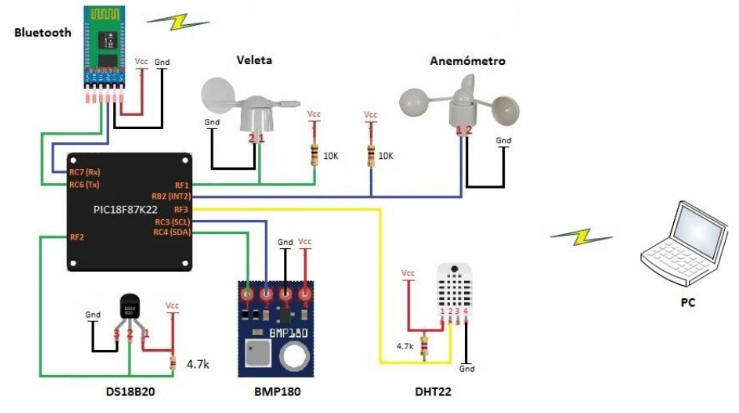
- Gómez Blázquez, A., "Autonomous low-power wireless sensor for a remote weather monitoring station", 2016. To examine the project documentation, download and unzip these two files: 1, 2.
|
|
|
Fig 5. Weather station representation and its final prototype. |
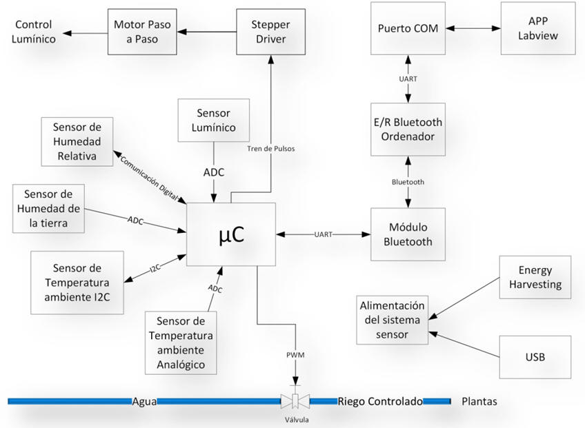
- García Moreno, A. "Autonomous low-power wireless sensor for greenhouse irrigation, 2016. To examine the project documentation download and unzip these two files: 1, 2.
|
|
|
Fig 6. Greenhouse irrigation system block diagram. |
|
Remarks on projects in engineering context: Students design solutions for a problem for which there is no single answer. The problem may require students working in cooperative groups to design a combination of plans, schematics, models, diagrams, simulations, source files and presentations. Going through the design process (specify, plan, develop and test) will require students to constantly adjust and modify their solutions to meet criteria. While designing a solution, it will be important to recognise that the idea of failure in engineering is a sign of growth in the cognitive process. Therefore, students may not get a viable solution on the first try or within the provided time constraints. In that case, the instructor can encourage them to reflect on their solution to identify what they have learned and look back to identify and correct design errors. |
| Home Term 24/25-Q1 Contact Products Electronic devices and companies Software Books Magazines Instruments DEE Library EETAC DEEL |

|
|
| Web activa des de 09/2001, @ F. J. Robert, J. Jordana. Web editat amb Microsoft Expression Web 4. El contingut és un complement als materials d'estudi del curs Circuits i Sistemes Digitals disponibles al campus digital Atenea. Llicència:Reconeixement 4.0 Internacional de Creative Commons |