|
|
Bachelor's Degree in Telecommunications Systems and in Network Engineering |
|
|
CLK circuits |
||
RC, quartz crystal and other oscillators
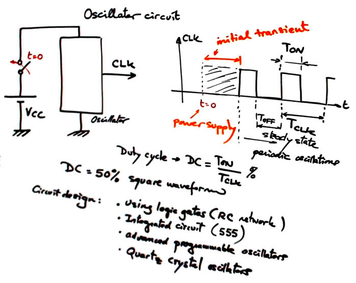
The idea of an oscillator circuit is represented in Fig. 1.
 |
|
Fig. 1. Symbol and concept of an oscillator circuit. |
The idea of oscillation based on NOT gates.
Fig. 2 shows a circuit that will freely oscillate using the sextuple 4069UB chip. If VDD = 5V, calculate its oscillation frequency. Demonstrate how it works simulating the circuit in Proteus and compare results.
|
Fig. 2. Exemplarising the concept of digital oscillator using inverters. |
2.3.2. CLK Circuits
2.3.2.1. RC circuit
RC oscillator
Fig. 3 shows the typical RC oscillator based on logic gates. This is the circuit RC_CLK in Proteus. Slide.
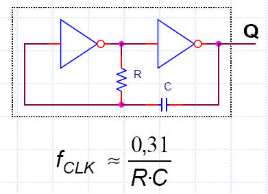 |
Fig. 3. Typical RC oscillator. Time constant determines the circuit oscillation frequency along with technology values associated with low and high logic margins. |
The analysis in Fig. 4 shows how to deduce its oscillation frequency.
| oscillation frequency |
Fig. 4. Analysis for deducing oscillation frequency. |
The circuit represented in Fig. 5 is a typical application to generate a sound wave (ref. Rudolf F. Graf, The encyclopaedia of electronic circuits, volume 6).
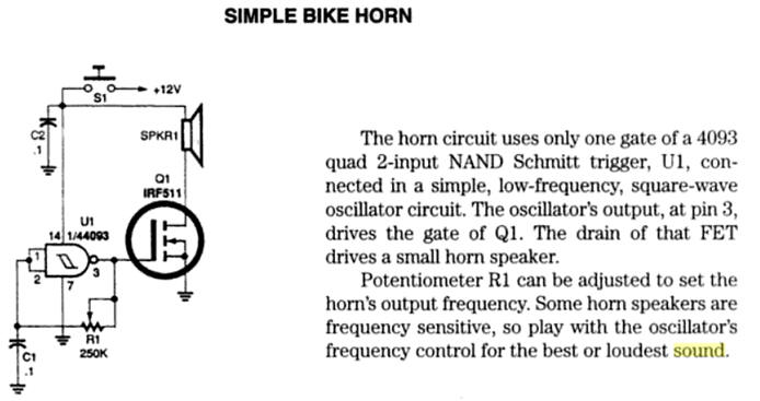 |
Fig. 5. Oscillator for a bike horn. It oscillates when clicking the button S1 that connects power supply. Try to simulate the circuit using Proteus and be aware on how the audible frequency can be adjusted using R1. |
2.3.2.2. Integrated circuit 555 oscillator
Oscillator based on 555 chip
Fig. 6 shows the typical 555 IC oscillator where RC components determine the frequency of oscillators with higher precision than in circuits based on logic gates. This is the circuit 555_CLK in Proteus for experimentation. Waveform duty cycle is also modulated if required.
 |
Fig. 6. Typical 555 oscillator. |
The analysis in Fig. 7 shows how to deduce its oscillation frequency.
| oscillation frequency |
| Fig. 7. Analysis for deducing oscillation frequency. |
And this DS1073 is an advanced programmable CLK chip.
2.3.2.3. Quartz crystal oscillator
Quartz crystal oscillator
Fig. 8 shows typical crystal oscillators. Wikipedia entry on crystal oscillators.
 |
Fig. 8. Example oscillator using a quartz crystal and a simple logic gate. |
 |
|
|
|
|
|
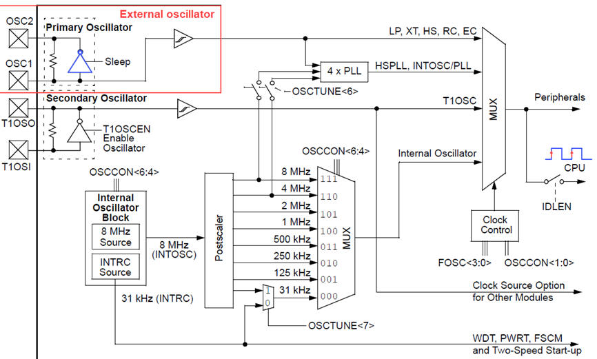
Fig. 9. PIC18F CLK options where an external quartz crystal can be wired between pins OSC1 and OSC2. |
|
DE10-Lite CLK circuit
This is the CLK chip populating the DE10-Lite board: Texas Instruments CDCEx937, flexible low power LVCMOS clock generator. The CDCE937 and CDCEL937 devices are modular PLL-based low cost, high-performance, programmable clock synthesizers, multipliers and dividers. They generate up to 7 output clocks from a single input frequency. Each output can be programmed in-system for any clock frequency up to 230 MHz,
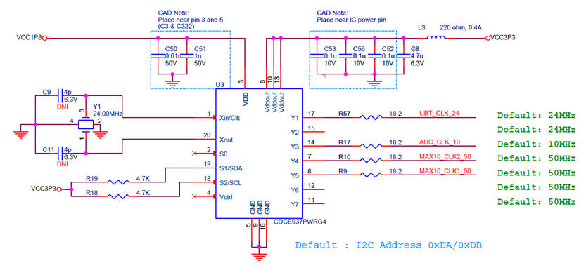 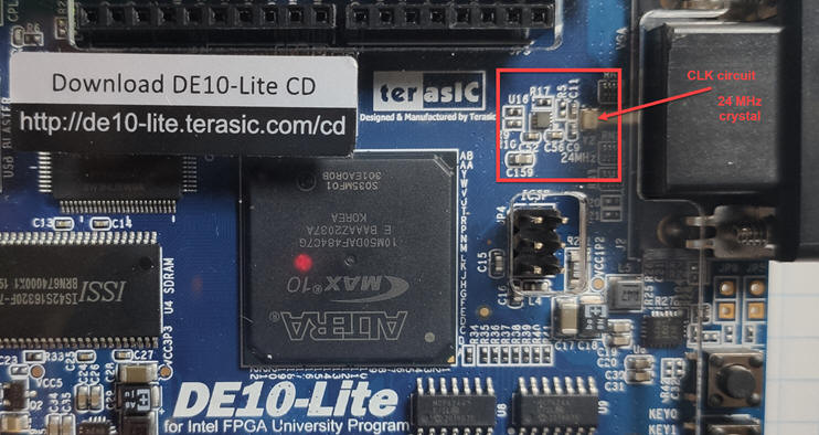 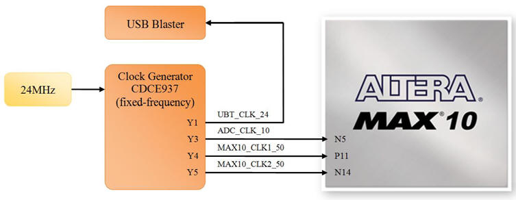 |
| Fig. 10. Details on DE10-Lite board CLK circuit. From a 24 MHz quartz crystal, the chip CDCE937 generates the several output CLK signals of 10 MHz, 24 MHz and 50 MHz. Two 50 MHz are available at the FPGA MAX10 at pins P11 and N14. |
News on the use of atomic clocks
This is a news article on "After 84 Years, Canada Stops Broadcasting Time From Its Atomic Clocks", All About Circuits, 2023,
| Home Term 24/25-Q1 Contact Products Electronic devices and companies Software Books Magazines Instruments DEE Library EETAC DEEL |

|
|
| Web activa des de 09/2001, @ F. J. Robert, J. Jordana. Web editat amb Microsoft Expression Web 4. El contingut és un complement als materials d'estudi del curs Circuits i Sistemes Digitals disponibles al campus digital Atenea. Llicència:Reconeixement 4.0 Internacional de Creative Commons |