|
|
|||||
Chapter 1 problems |
- A1.5 - |
Analysing Circuit_N |
|||
|
|
|||||
Specifications
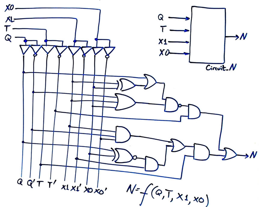
Determine the truth table of Circuit_N proposed in Fig. 1 using the following analysis methods (L1.3):
- Method I: pen & paper handwritten solution using algebraic equations and simplifications. Project location:
C:\CSD\P1\Circuit_N\Algebra\(files)
- Method II: Proteus with CMOS or LS-TTL librares. Project location:
C:\CSD\P1\Circuit_N\Proteus\(files)
- Method III: VHDL EDA tools: synthesis & simulation. Project location:
C:\CSD\P1\Circuit_N\VHDL\(files)
- Method IV: WolframAlpha. Project location:
C:\CSD\P1\Circuit_N\Wolfram\(files)
|
|
|
Fig. 1. Symbol and internal architecture of Circuit_N. |
Each analysis method requires to be placed in the project location indicated above.
Each project report contains at least 4 sheets of paper, one sheet per section. You can add your theory or other learning materials in section 1 on specifications of one of your projects.
NOTE: be aware that projects developed in other computer locations are NOT corrected or marked.


