|
|
Bachelor's Degree in Telecommunications Systems and in Network Engineering |
|
|
L8.1: Dedicated processors [P8] Advanced digital System architecture: Datapath + Control unit + CLK generator |
[19/11] |
2.8. Dedicated processors or subsystems
2.8.1. Architecture of an advanced digital system
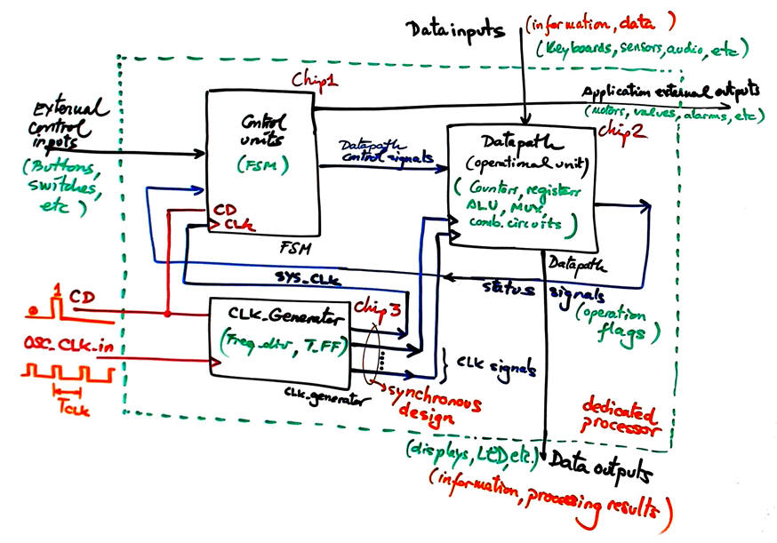
2.8.2. Datapath (operational) unit, data input/output, status signals and flags
Datapath (registers and ALU (aritmetic and logic circuits: add, substract, multiply, shift, count, etc.)
2.8.3. Control unit (FSM). Control signals, external inputs and outputs
Another example of advanced digital circuit, run the HH:MM:SS example real-time clock available in Proteus in P8 and realise how many more counters can be organised in the same way applying the plan C2 ideas on counter truncation and hierarchical design.
Exercise: Design the block diagram of a 10-bit serial adder. The datapath contains only an Adder_2bit as the component to perform operations. Complet the datapath and explain the required state diagram in the contrl unit. Analyse this similar tutorial Adder_4bit serial adder to get the notions to infer the block diagram of this dedicated processor.
| Home Term 24/25-Q1 Contact Products Electronic devices and companies Software Books Magazines Instruments DEE Library EETAC DEEL |

|
|
| Web activa des de 09/2001, @ F. J. Robert, J. Jordana. Web editat amb Microsoft Expression Web 4. El contingut és un complement als materials d'estudi del curs Circuits i Sistemes Digitals disponibles al campus digital Atenea. Llicència:Reconeixement 4.0 Internacional de Creative Commons |