|
|
Bachelor's Degree in Telecommunications Systems and in Network Engineering. Bachelor's Degree in Aerospace Systems Engineering |
|
Laboratory 2: Electronic equipment Hardware & software. Training boards. Prototyping |
Objectives |
Electronic equipment |
Arduino |
Design project |
We propose three objectives for this lab session that will imply studying initial theory on electronic equipment architectures, running an activity on Arduino and designing a project on anaolgue circuits.
(1) Discuss the typical standard electronic equipment architecture found in most applications: data acquisition and control systems, data loggers, digital instruments, digital controllers, dedicated processors and all kind of subsystems.
(2) Review common training boards for prototyping electronic circuits. Run and analyse an Arduino application example on Proteus virtual laboratory.
(3) Calculate, mount and solder a sample circuit in an universal PCB. For instance, design and test an analogue voltage amplifier with G = -10. Power it using (a) dual power supply voltage VCC = +5 V and VEE = -5 V, (b) single VCC = +5 V.
Objectives |
Electronic equipment |
Arduino |
Design project |
Electronic equipment. Introduction. State of the art. Context.
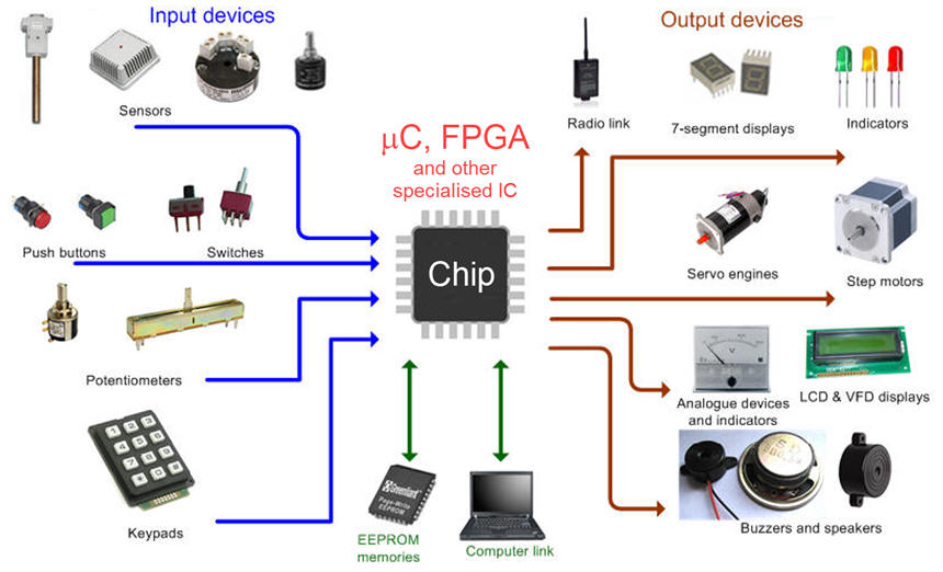
We can imagine electronic equipment examples organised around these three main sections:
(1) inputs: sensors (digital and analogue with circuit conditioners), buttons, switches, keyboards.
(2) microcontroller and FPGA boards.
(3) outputs: LED, displays, analogue gauges, sound devices, data memories, motors and other actuators.
|
|
|
Fig. 1. Modern electronic equipment build around a digital microcontrollers or specialised hardware devices. |
Find examples of block diagrams of digital equipment. For instance, Fig. 2 shows the main components of a control system for a steper motor.
|
|
|
Fig. 2. Example of a system for controlling the position of an stepper motor. |
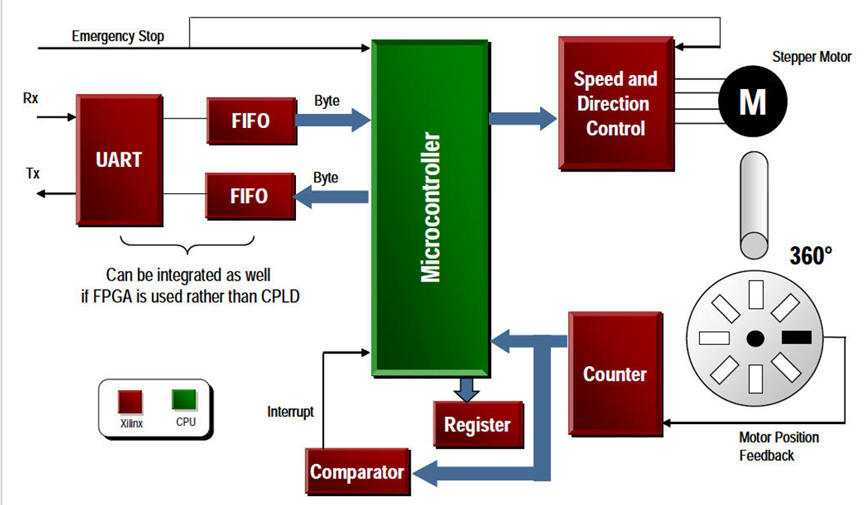
Fig. 3 enumerates the many electronic subsystems currently available in a modern car.
|
|
|
Fig. 3. The myriad of applications of electronic systems in automobile industry (ref.). A long list of projects. |
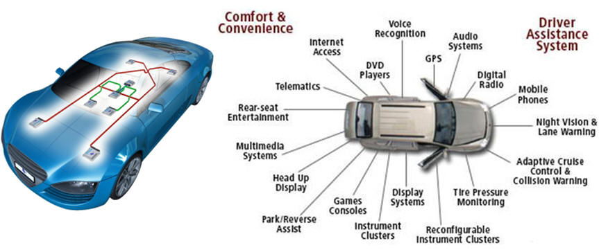
Fig. 4 shows the block diagram of a medical device for heart monitoring.
|
|
|
Fig. 4. Digital medical devices are fueling a revolution in health care. This is heartbeat monitoring and alert system (ref.). |
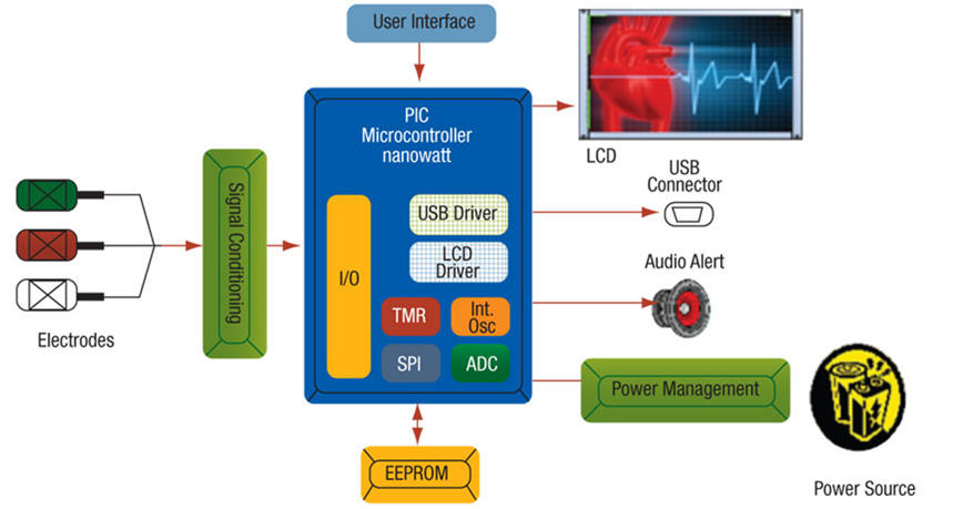
Fig. 5 lists the many features associated to a battery powered instrument.
|
|
|
Fig. 5. Wind speed meter instrument (ref.) |
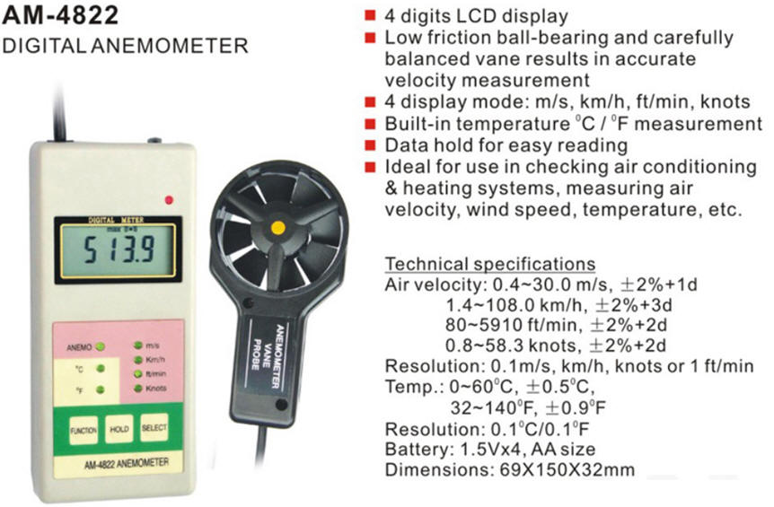
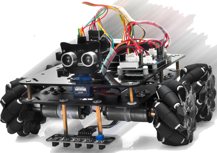
Fig. 6 shows an educational kit for introducing students and hobbyist in this world of electronic equipment design. When mounting a robotic car step by step its is possible to get a good idea on how mechanical parts, sensors, controllers, actuators and communications devices work together.
|
|
|
Fig. 6. An educational kit for students and hobbyist. (ref). This model includes Mecanum omni-wheels. |
Find definitions and compare microcontrollers and FPGA. Advantages and disadvantages.
Training boards
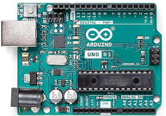
(1) Arduino is one of the most well known and popular boards.
|
|
Fig. 7. Arduino UNO board. |
Hardware Print the circuit schematic and start examining it to deduce its main uilding blocks. This is an reference article from an online magazine Tawil, Y. Understanding Arduino UNO Hardware Design, All About Circuits, 2016.
Name and explain the function of the two microcontrollers. Which is the interface between them?
How does the OSC work? What is the OSC frequency?
How does the reset button work?
-
How many digital I/O contains the board? What is the maximum current that any of these outputs can sink or drain?
-
How many analogue input channels are included in the board?
-
More questions for LAB3 on power circuits:
Software development environment: Arduino IDE. Installed in LAB1.
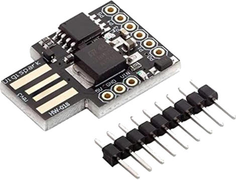
(2) Other Arduino software based boards. For instance: Digispark Attiny85 board (1). You can even build yourself using KiCad as shown in this video (2).
|
|
Fig. 8. Digispark ATtiny85 microcontroller board can be connected directly to the computer USB port. This is the microcontroller ATtiny85 from Microchip. |
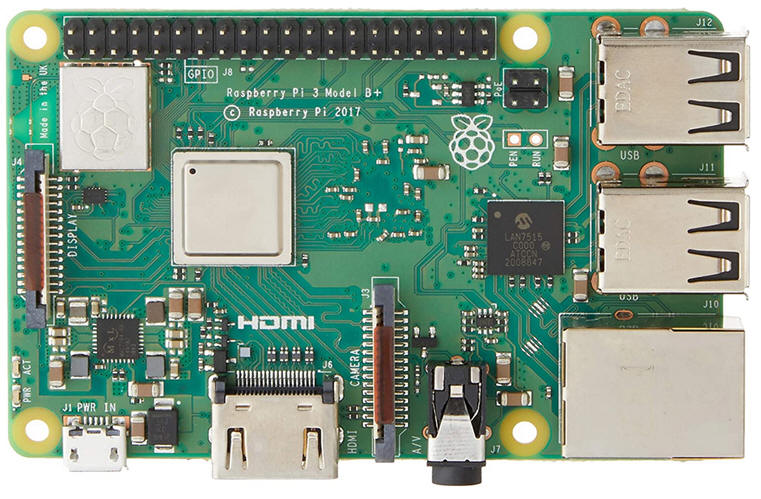
(3) Raspberry Pi
This is another well known and popular computer card size board.
|
|
Fig. 9. Raspberry Pi 3 model B+ |
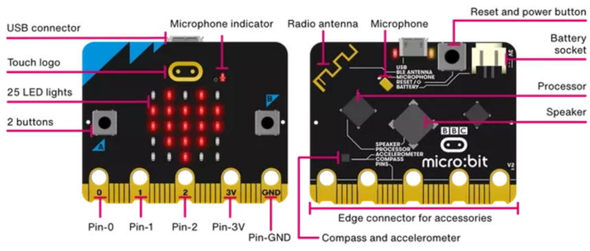
(4) micro:bit
Specially configured for introducing electronics and programming to young learners
|
|
| Fig. 10. Micro:bit board |
(5) FPGA boards for hardware projects
Terasic Intel DE10-Lite. This FPGA-based training board can be used for two specific and differentiated purposes: (1) as a hardware platform for curstom high speed digital circuit projects, (2) as a hardware and software platform for embedded systems on chip.
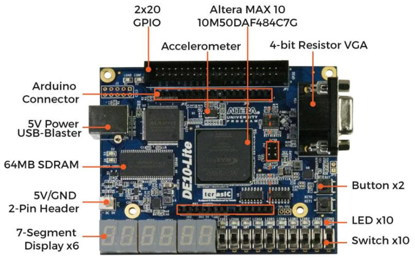 |
| Fig. 11. Terasic DE10-Lite with a MAX10 FPGA from Intel. |
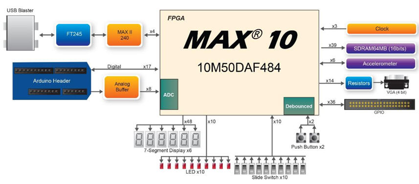
Altera (Intel). Learn basic digital electronics, as we currently propose at the EETAC (Digsys). DE10-Lite is a platform where to synthesise combinational circuits and sequential systems at RTL (register-transfer level) using VHDL techniques.
|
|
|
Fig. 12. DE10-Lite diagram when used as a platform for learning digital circuits around MAX10 Intel FPGA. |
AMD (Xilinx). Another example of this kind is Digilent Arty board including the Xilinx (AMD) Artix -7 FPGA.
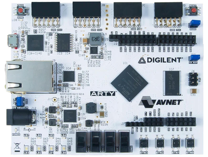 |
| Fig. 13. Digilent Board Arty with an Artix -7 FPGA XC7A35T-1CSG324-1L from Xilinx (now AMD). |
(6) FPGA boards for hardware and software projects (embedded systems on chip)
System builder. Embedded microcontrollers.
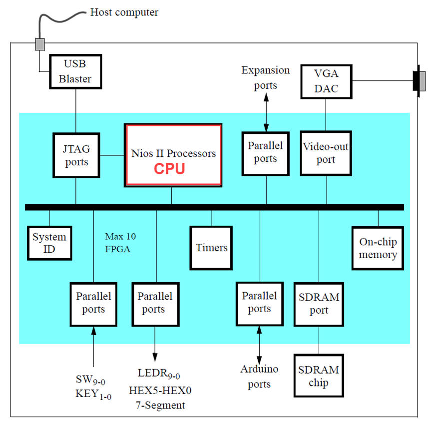
Altera (Intel) Learn the introductory concepts on advanced embedded system-on-chip design. We can integrate a μC in the FPGA fabric.
|
|
Fig. 14. DE10-Lite diagram when used for learning embedded systems based on microcomputers. At this introductory level, NIOS II soft processor is offered as CPU (ref.) |
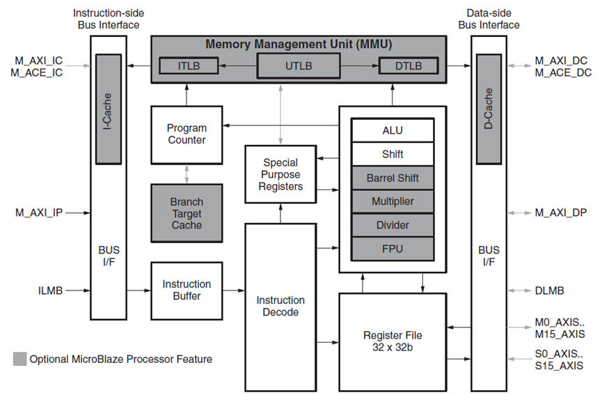
AMD (Xilinx). In the FPGA fabric a soft processor such Microblaze can be synthesised and used in introductory designs and applications.
|
|
Fig. 15. Microblaze embedded CPU or MicroBlaze Soft Processor Core block diagram (ref.) |
Some questions intended to review these materials:
- Compare the main features of the three training boards. Find another training board of the same kind and analyse its architecture.
- Find examples of sensors, actuators and peripherals used in telecomunications, aeronautics or other industries.
Objectives |
Electronic equipment |
Arduino |
Design project |
Studying the Arduino board |
| 1. Specifications | Planning | Dev. & test | Prototype | Report |
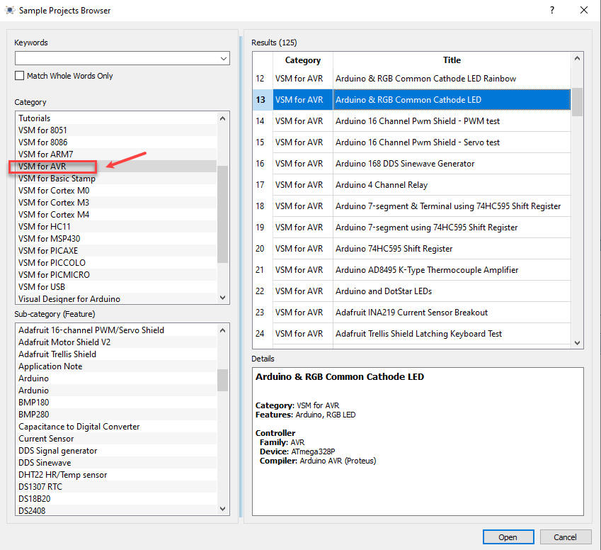
Browse some books or internet pages to find a sample Arduino project application and rename it Circuit_1. Try to find an example easy to be captured in our simulator Proteus, for example from the same samples examples included in Proteus.
| Specifications | 2. Planning | Dev. & test | Prototype | Report |
Find a Proteus sample project based on the Arduino platform. Compile the code. Run and test in the simulation platform. Upload the code to the Arduino board, complete the circuit using a breadboard, run, test and measure waveforms using laboratory instrumentation.
|
|
Fig. 1. Proteus list of examples circuits including Arduino or other microcontrollers. We have bought a school license for running Arduino and PIC18F microcontroller applications. |
Project folder:
C:\DEE\LAB2\Circuit_1\(files)
| Specifications | Planning | 3. Dev. & 4. Test | Prototype | Report |
Developing
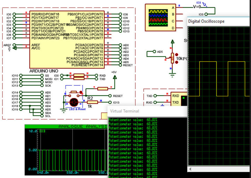
Circuit_1: For example Circuit_1.pdsprj captured in Proteus. Using this initial circuit we will verify that the software is correctly installed and capable of simulating microcontroller applications. From LAB4 we will use Proteus as the hardware platform accompanying the Microchip MPLABX-XC8 for developing and debugging Arduino-based projects.
|
|
Fig. 2. Screen capture showing the application running interactively. |
Testing
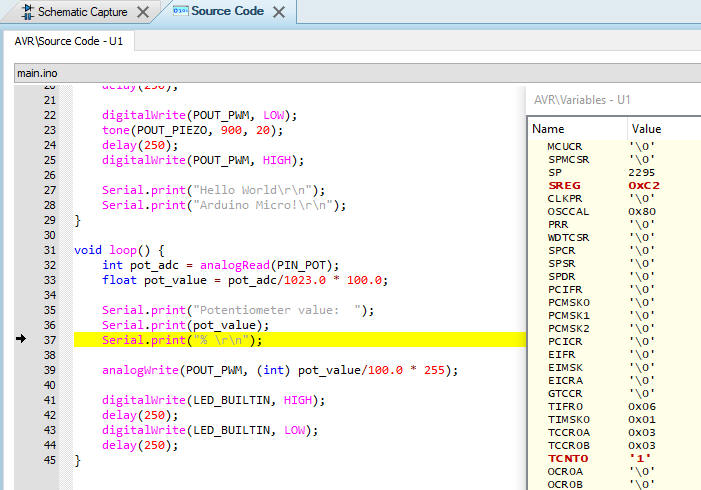
Run Circuit_1 interactively and step by step execution modes, show ATmega328P and program variables, open a watch window for the variables of interest, etc.
|
|
Fig. 3. Screen capture of the source code showing the step-by-step mode execution. |
| Specifications | Planning | Dev. & Test | 5. Prototype | Report |
Download the configuration file (*.hex) to the Arduino board from the Proteus programmer interface or directly from Arduino IDE.
Complete the circuit using a breadboard and verify the design.
Measure parameters and waveforms using the instrument VB8012.
| Specifications | Planning | Dev. & Test | Prototype | 6. Report and postlab assignments |
Reporting this project will look like these pages. Organise it in the same five sections in at least five sheets of paper.
(1) Specifications. As the theory accompanying the specifications, you can:
- Find an example of digital equipment for aerospace systems. Study its architecture and compare with the example architectures given in this lab.
- Find a sensor in Proteus libraries. Print the schematic and its features from the datasheet.
- Find an actuator in Proteus libraries. Print the schematic and its features from the datasheet.
(2) Planning. Print your Proteus example that includes a microcontroller. Analise the C code and draw its equivalent flowchart.
(3) Development and (4) Testing. Print an example image showing how the circuit works interactively including the watch window with some RAM variables of interest. Print/a> the software listing and analyse and draw its flowchart.
(5) Prototyping. Print a picture of your circuit running in the Arduino platform. Print the instrument screen representing signals.
Objectives |
Electronic equipment |
Arduino |
Design project |
Design project on analogue circuits: OpAmp amplifier |
| 1. Specifications | Planning | Dev. & test | Prototype | Report |
Design a dual power supply (Vcc = +5 V, Vee = -5 V) small signal analogue amplifier. Voltage gain = -10. RL = 3.3 kW
Get used to basic laboratory components and equipment.
Proteus simulation of analogue circuits.
Build and solder an inverter amplifier using a universal PCB.
KiCad PCB introduction.
Topics in EMC
Start to figure out how to shield the amplified in Fig. 4 against EMI. How to reduce coupled noise and improve the circuit's signal/noise ratio?
What about the resistor values? What are the tradeoffs if the gain ratio is solved using MW resistors or kW resistors? What is and how to calculate thermal noise associated to resistors?
Identify noise signals and measure the amplifier sensitivity: which is the minimum input signal above noise floor?
| Specifications | 2. Planning | Dev. & test | Prototype | Report |
Let us imagine an OpAmp simple non-inverter amplifier. Calculate: R1 = 2.2 kW, R2 = 22 kW.
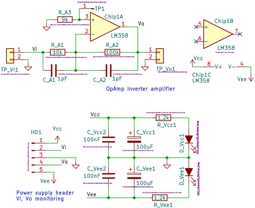
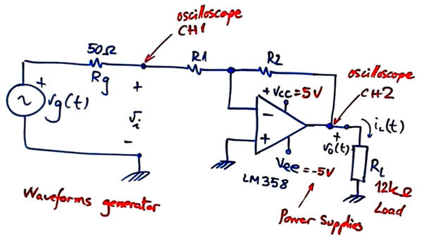 |
| Fig. 1. Inverter amplifier sketch. |
This amplifier project will be located at:
C:\DEE\LAB2\Amplifier\(files)
C:\DEE\LAB2\Amplifier\Proteus\(files)
C:\DEE\LAB2\Amplifier\PCB\(files)
| Specifications | Planning | 3. Dev. & 4. Test | Prototype | Report |
Simulate the circuit in Proteus Amplifier.pdsprj.
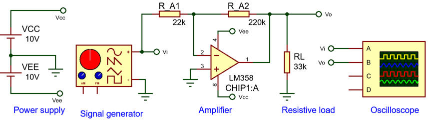 |
| Fig. 2. Circuit captured in Proteus using the LM258 OpAmp circuit. |
Run simulations using oscilloscopes and signal generators.
Measure its small signal -3dB bandwidth using the graphic frequency response analysis.
 |
| Fig. 3. Example of frequency response using graphic analysis. |
Choose different OpAmp components and power supplies and observe how they work when large signals reach power supply rails.
| Specifications | Planning | Dev. & Test | 5. Prototype | Report |
Experimentation and measurements
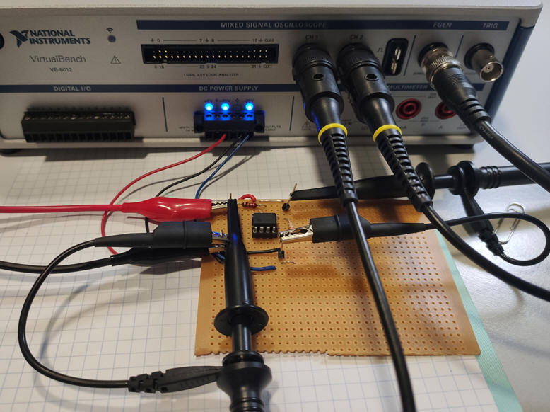
Mount the circuit in a prototyping board or in a PCB. Characterise the circuit using the VB8012 instrument.
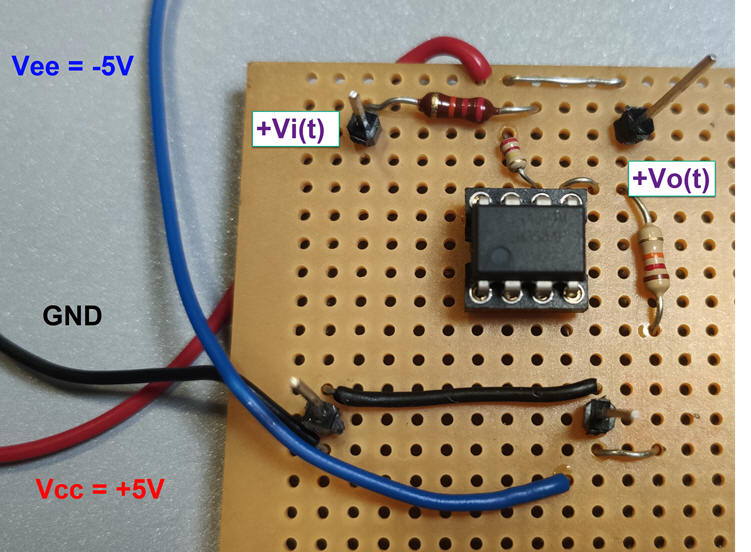 |
| Fig. 4. Prototype for an inverter amplifier. R1 = 22 kW built using a universal board. |
Find the circuit's bandwidth BW-3dB using sinusoidal waveforms and the function generator. Find the circuit rising time Tr using square waves.
Measure using 1:1 probes. Measure using 10:1 probes.
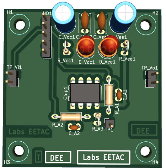
|
|
Fig. 5. Picture of the example circuit soldered in a universal PCB for prototyping purposes. |
Print outputs from instruments and simulators to demonstrate that the circuit works as expected within its bandwidth and output dynamic range.
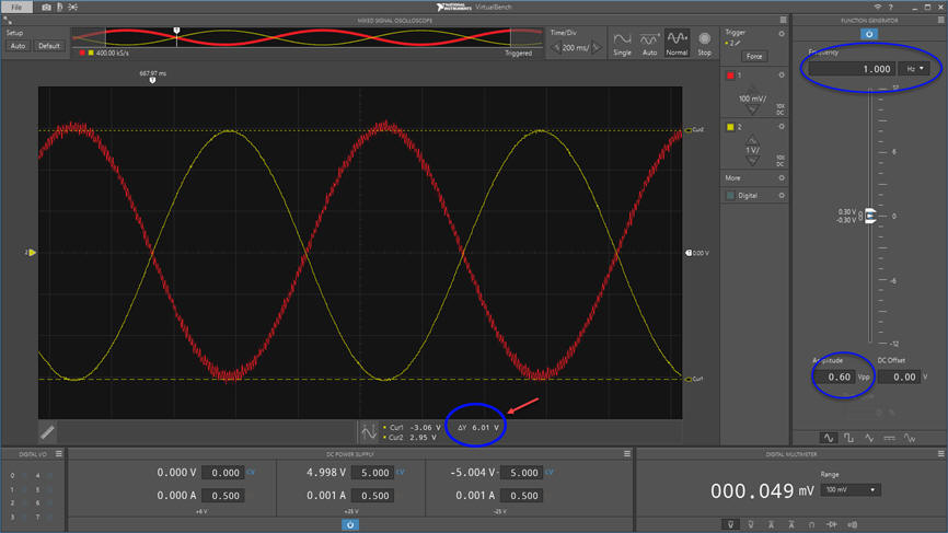 |
| Fig. 6. Measured waveforms when input is 0.3 Vp and fin = 1 kHz |
Think about on how to reduce the noise captured by the input CH1. Which is the frequency of the interference? What may it be its cause? What components can be added to this prototype to shield the circuit against electrical noise?
PCB design using KiCad
This Amplifier.zip project is an example of schematic capture and PCB design using KiCad.
Kicad PCB files: Amplifier_PCB_KiCad.zip
NOTE: Current CSD and DEE KiCad symbols, footprints and 3D tuned components are available in these three libraries: symbols.zip, footprints.zip and 3dmodels.zip, to be unzipped and placed in the corresponding 3rdparty user directory. Basically, in this introductory level the idea behind tunnig components is to enlarge their pads for easy soldering.
|
|
Fig. 7. Schematic capture in KiCad. |
A good component placement will help to reduce the length of the PCB tracks while reducing the total number of vias between top and bottom layers.
|
|
|
Fig. 8. Example silkscreen printing representing component placement. |
KiCad offers the 3D view of the PCB under design, which is quite convenient to have a good idea on how the final prototype will look like once fabricated.
|
|
|
Fig. 9. Example 3D view of the prototype in KiCad. |
| Specifications | Planning | Dev. & Test | Prototype | 6. Report and postlab assignments |
Studying and reporting this LAB2 means designing and characterising the amplifier. Your report contains at least five sections of handwritten sheets of paper and printed images from circuits.
(1) Specifications. Use diagrams and sketches, represent the symbol and model of the amplifier. Draw an example timing diagram using sinusoidal waveforms. Explain how a microfon can be connected to such amplifier.
(2) Planning. Propose a circuit and calculate its components. Propose alternative circuits discussing advantages and drawbacks.
(3) Developing. Simulate your circuit and check that it works as expected in the specifications. Take pictures or print graphics from simulators and analyse and discuss the results.
(4) Run simulations and test your circuit. Add or modify component values if necessary. Analise and discuss your results.
(5) Prototyping. Solder the circuit in an universal protoboard or in a PCB. Experiment performing measurements to characterising the circuit. Discuss how the circuit adjust to the specifications.
Additional questions to be included in the report discussion:
-
Calculate the minimum input signals that can be distinguished from noise.
-
Calculate the output voltage maximum span and represent the Vo= f(Vi) function from X-Y
-
Measure the power consumed by this circuit.
-
Discuss how to adapt the circuit to a single +5 V power supply for amplifying audio signals from 20Hz to 20 kHz.
| Home Contact Electronic devices and companies Books Magazines Instruments Digsys Library EETAC DEEL |

|
|
| Web activa des de 01/2023, @ F. J. Robert. Web editat amb Microsoft Expression Web 4. El contingut és material de referència per al disseny d'equips electrònics. Llicència:Reconeixement 4.0 Internacional de Creative Commons |