|
|
Bachelor's Degree in Telecommunications Systems and in Network Engineering. Bachelor's Degree in Aerospace Systems Engineering |
|
Laboratory 3 Power supplies, thermal analysis, voltage regulation and power consumption |
Objectives |
Power supplies |
Heatsinks |
Arduino |
Project |
After reviewing the main ideas behind typical AC/DC conversion techniques for powering electronic applications, our goals for this laboratory session will represent two projects:
(1) Study how the Arduino board is powered.
(2) Design and prototype a constant-current AA - AAA 1.2 V nickel metal hydride (NiMH) battery charger.
Objectives |
Power supplies |
Heatsinks |
Arduino |
Project |
Basic context on power electronics
This is a good time for browsing the internet many resources on this topic. A convenient web to start:
![]()
Quantities and concepts of interest: voltage, power, current, energy, load resistance, electrical isolation and electrical security.
AC/DC adapters
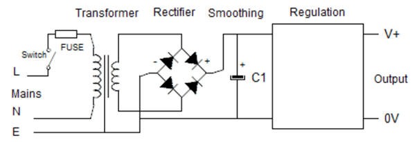
AC/DC power conversion from 50/60 Hz mains plug. Transformers have low power losses. The same with rectifier diodes that work as ideal switches. The smoothing capacitor simply accumulates energy. The voltage regulator is the critical block if our concern is power efficiency.
 |
|
Fig. 1. Block diagram of a typical power supply input front-end (ref.) |
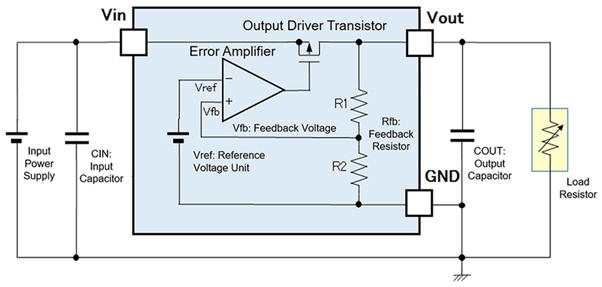
Linear voltage regulation
 |
|
Fig. 2. Typical linear regulator using operational amplifier to establish the feedback control loop (ref.) (ref.) |
Study some training boards power supply circuits. Focus your attention analysing the circuit for powering the Arduino board.
Linear current regulation
How to derive a current supply from a voltage supply? What is like your phone charger? Design a charger for AAA and AA batteries. How to add a timer, for instance, a 15 h timer, to the charger so that the charging process stops when batteries full? How much energy is lost (dissipated as heat) by the charger in the process of charging four AA batteries for 16 h?
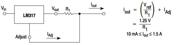 |
| Fig. 3. Typical adjustable current source where the control loop allows constant current to be selected. This circuit can be used as a battery charger (ref.) (ref.) (LM317 chip). LED driver may be as well designed using current sources. |
Switching DC/DC converters
Describe the currently used switching topologies for DC/DC conversion. Which is the design equation?
Buck converter. Step-down voltage.
 |
|
Fig. 4. Buck topology to convert power with high efficiently. (ref.). Equations in continuous conduction mode (CCM). |
Boost converter. Step-up voltage.
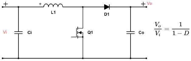 ç ç |
|
Fig. 5. Boost topology. Ref. TI power topologies handbook: slYu036.. Equations in continuous conduction mode (CCM). |
Inverting Buck-Boost converter. Step up/down voltage.
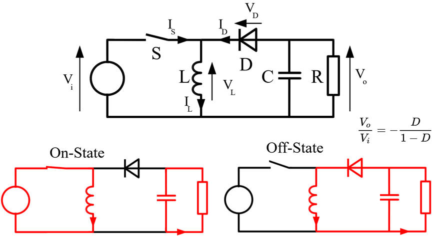 |
|
Fig. 6. Buck-Boost topology. (ref.). Equations in continuous conduction mode (CCM). |
Isolated power-converter Flyback topology.
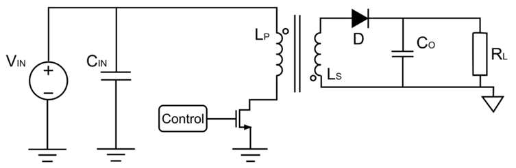  |
|
Fig. 7. Flyback topology offers the advantage of isolating input and output. (ref.) (ref.) |
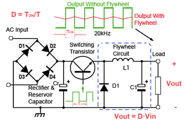
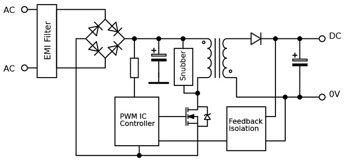
Non-isolated (off-line) power supply (only for very specific applications)
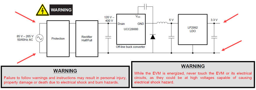 |
|
Fig. 8. Example block diagram of an off-line AC to DC Converter (ref. Design Guide: TIDA-010060 ) |
Objectives |
Power supplies |
Heatsinks |
Arduino |
Project |
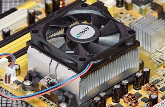
Thermal analysis. Heatsink calculations
Selecting mechanical heatsinks. Other references. Thermal resistance (qth) and junction temperature Tj. Design examples and equations.
 |
|
Fig. 9. Example of aluminum heatsink and fan to reduce thermal resistance (picture ref.). |
Design a 12 V / 4 A (48 W) linear power supply using AO and a Darlington BJT transistor pair. What is the advantage of using LDO voltage regulators? What are the heatsink requirements to keep the power transistors in their safe operating area? Why it may be necesssary to use a fan for extracting heat while keeping the semiconductors in safe operating conditions?
Objectives |
Power supplies |
Heatsinks |
Arduino |
Project |
Print the Arduino UNO schematic and try to deduce how it works. In which way the USB power is disconnected when an external Vin is plugged?
|
|
|
Fig. 9. Arduino UNO schematic where all the power supply circuitry can be analysed. |
What happens when for instance an external VIN = +12 V is connected directly to +5 V terminal?
How many regulated and unregulated voltages are available?
Find the datasheets of voltage regulator chips.
What is the maximum current/power available for each converter?
Calculate the maximum power available for powering board circuits and external circuits using both VIN connector and VDD from the USB.
Topics in EMC
Identify in the Arduino schematic the components added for EMC.
Objectives |
Power supplies |
Heatsinks |
Arduino |
Project |
Design a battery charger |
| 1. Specifications | Planning | Dev. & test | Prototype | Report |
Propose a circuit using an AC/DC voltage adapter that can be used to charge up to 6 AA - AAA 1.2 V nickel metal hydride (NiMH) batteries using fast and slow charge currents.
Prototype the charger, run simulations and laboratory measurements and design its PCB.
Add a timer to switch off the charger once the batteries are full.
Topics in EMC
What circuits have to be included to protect the charger against ESD?
| Specifications | 2.Planning | Dev. & test | Prototype | Report |
Calculate the schematic components. Select the transistors and integrated circuits. Does it require a heatsink?
This project will be located at:
C:\DEE\LAB3\Battery_charger\(files)
| Specifications | Planning | 3. Dev. & 4. Test | Prototype | Report |
We can calculate and simulate a linear voltage regulator in Proteus or Multisim.
We can start with this example battery charger simulated in Proteus. Adapt it to our specifications.
| Specifications | Planning | Dev. & Test | 5. Prototype | Report |
PCB design
Use the previous project PCB as a template for making the battery charger PCB.
This PCB project will be located at:
C:\DEE\LAB3\Battery_charger\PCB\(files)
Mount the circuit and perform measurements to check that the circuit works as expected. You can use a battery discarger to speed up your experiments.
Experimentation and measurements
| Specifications | Planning | Dev. & Test | Prototype | 6. Report and postlab assignments |
Studying and reporting this LAB3 represents at least five sections of handwritten sheets of paper and printed images from the battery charger circuits.
| Home Contact Electronic devices and companies Books Magazines Instruments Digsys Library EETAC DEEL |

|
|
| Web activa des de 01/2023, @ F. J. Robert. Web editat amb Microsoft Expression Web 4. El contingut és material de referència per al disseny d'equips electrònics. Llicència:Reconeixement 4.0 Internacional de Creative Commons |