|
|
Bachelor's Degree in Telecommunications Systems and in Network Engineering |
|
|
|
|||
|
|
6-bit Johnson sequencer with ST/SP button (design phase #2) |
|
|
|
|
|||
Johnson sequencer with LCD display (phase #2)
(Under revision)
1. Specifications
Implement Johnson_sequencer_mod12 using a PIC18F4520 microcontroller chip. Software is organised mimicking a FSM and interrupt-driven to attend edge-triggered inputs such start/stop pushbutton and CLK.
 |
Fig 1. Symbol of the device to be designed. |
Features:
- Same features reported in P10 tutorial: Johnson_sequencer_mod12 (design phase #1).
- Add an LCD to show represent the LED sequence using special characters on the LCD display.
2. Planning
A) Planning hardware
Represented in Fig. 3.
|
Fig. 3. Circuit. |
B) Planning software
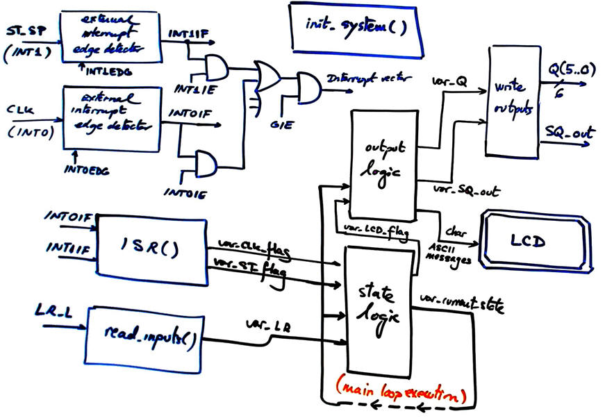 |
Fig. 4. Hardware-software diagram highlighting small modifications in output_logic() for connecting the LCD. |
Draw the state diagram, only considering what is modified with respect the design phase #1.
|
Fig. 5. State diagram proposal. |
Represent the new RAM variables required in this application.
|
Fig. 6. New RAM variables. |
Draw the main ideas of init_system(). Configure input and output pins. Consider as well interrupts configuration.
|
Fig. 7. Data direction registers configuration. |
Draw the flowchart of read_inputs(). Basic function to poll input voltages as in P9.
Draw the flowchart of write_outputs(). Basic function to write pin voltages as in P9.
Infer how to organise the interrupt service routine ISR() to handle edge detections.
Draw state_logic() truth table
|
Fig. 8. State logic function (CC1). |
|
Fig. 9. State logic flowchart is a behavioural interpretation of the truth table. |
Draw output_logic() truth table.
|
|
Fig. 10. Output logic function (CC2). |
|
|
Fig. 11. Output logic flowchart is a behavioural interpretation of the truth table. |
Organise a MPLABX - XC8 IDE project targetting a PIC18F4520 at location:
C:/CSD/P10/Johnson_sequencer_mod12/(files)
3. Development - 4. Testing interactively
A) Developing hardware
Example circuit: Johnson_sequencer_mod12_LCD.pdsprj.
B) Developing software
These are the LCD library functions and the source code modified to include the control of the LCD Johnson_sequencer_mod12_LCD.c.
C) Step-by-step testing
Run the Proteus simulator. Do it in step by step mode while watching variables and placing break points, specially for following interrupt flags.
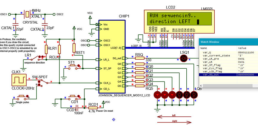 |
| Fig. 13. The circuit in "run" mode while monitoring the variables in the "watch" window. |
5. Report
6. Prototyping
You are invited to download the application to a given training board an verify that it works as expected and the same as in the simulator.
| Home Term 24/25-Q1 Contact Products Electronic devices and companies Software Books Magazines Instruments DEE Library EETAC DEEL |

|
|
| Web activa des de 09/2001, @ F. J. Robert, J. Jordana. Web editat amb Microsoft Expression Web 4. El contingut és un complement als materials d'estudi del curs Circuits i Sistemes Digitals disponibles al campus digital Atenea. Llicència:Reconeixement 4.0 Internacional de Creative Commons |