|
|
Bachelor's Degree in Telecommunications Systems and in Network Engineering. Bachelor's Degree in Aerospace Systems Engineering |
|
|
LCD and other displays. I2C and SPI buses, digital sensors and actuators. |
| 1. Specifications | Planning | Dev. & test | Prototype | Report |
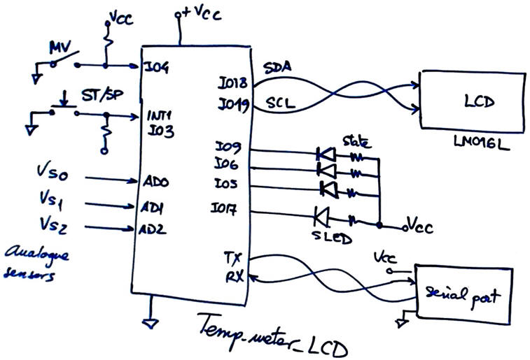
Our goal is to add an LCD to our temperature measurement system inherited from LAB6. Let us use it for representing ASCII messages and numbers showing temperature values and FSM states. An alternative system or complementary representation to the serial port.
The schematic of our application is represented in Fig. 1.
|
|
|
Fig. 1. Adding an LCD display to our data acquisition system. |
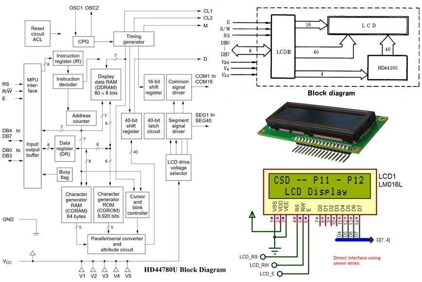
One of the simplest LCD displays available is the LM016L represented in Fig. 2, already studied in detail in P11 where it is directly interfaced to a PIC microcontroller system using seven wires: 3 control lines (E, RS and R/W) and a DB(7..4) data bus for sending messages and commands.
|
|
|
Fig. 2. LM016L board that is also simulated as a component in Proteus. |
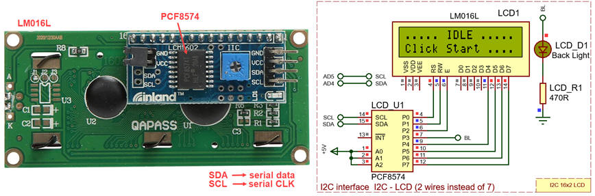
Arduino does not have that number of available I/O pins if we are thinking on inheriting and enhancing previous projects, thus we will consider the alternative connection shown in Fig. 3 using only the 2-wire bus I2C explained in detail in the section below.
|
|
|
Fig. 3. LM016L connected to an 8-bit input/output (I/O) expander for the two-line bidirectional bus (I2C) to simplify the hardware connection to a microcontroller such Arduino. This is the PCF8574 datasheet. |
I2C bus
SPI bus
Topics in EMC
| Specs | 2. Planning | Dev. & test | Prototype | Report |
Hardware
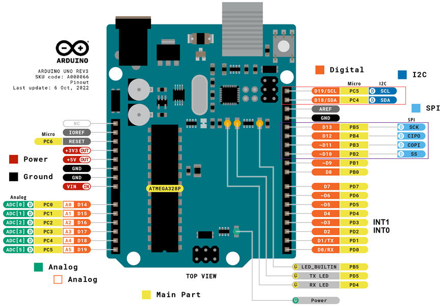
I2C port is available in Arduino at IO18 (SDA) and IO19 (SCL). Using I2C interface implies that AD4 and AD5 are not available. The same drawback happens with the SPI bus used by many more sensors and devices. If the SPI port is used, IO13, IO12, IO11 and IO10 are no longer available as digital inputs or outputs.
|
|
|
Fig. 4. Arduino UNO board hardware (ref.) |
Software
The key idea on using such complex peripherals and buses is the library of functions that will make easy programming the device. The other idea is to write the LCD only when there is new information to display, this is why a new indicator is used: var_LCD_flag = 1 when there is new information to write on the LCD.
Project location:
C:\DEE\LAB7\Temp_LCD\(files)
| Specs | Planning | 3. Dev. & 4. Test | Prototype | Report |
Hardware
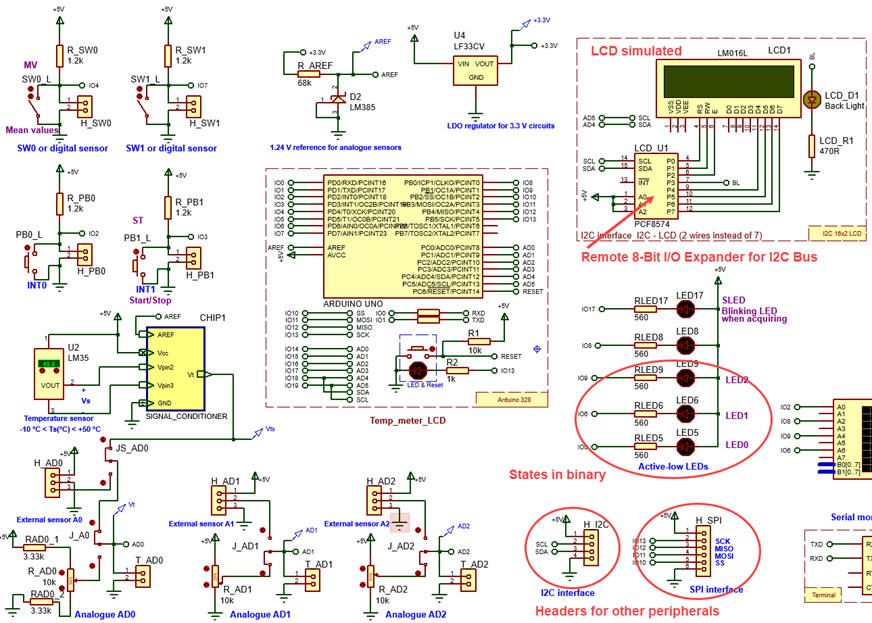
We can take full advantage of Proteus virtual laboratory copying and enhancing LAB6 projects adding I2C (and SPI) headers where to connect the LCD and other sensors or actuators. Temp_LCD.zip.
|
|
|
Fig. 5. Board including the LCD. |
Software
Indications on how to install the LCD I2C library are posted in this CSD similar example Temp_meter.
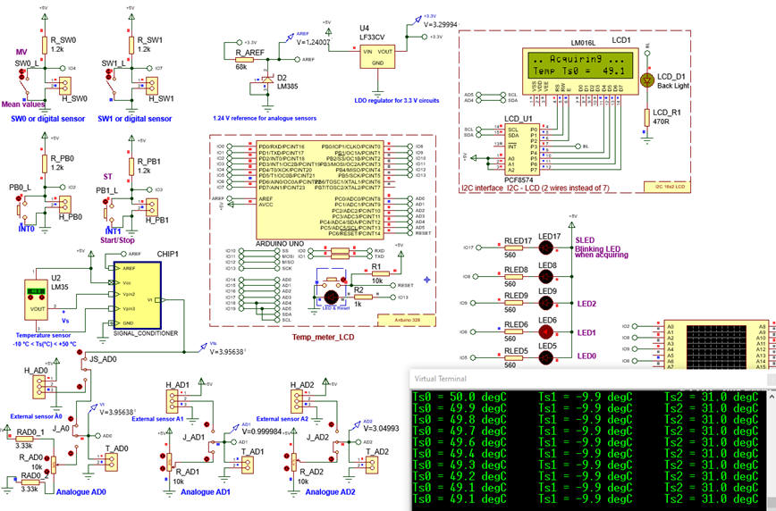
Fig. 6 shows the board running representing temperatures in the LCD screen.
|
|
|
Fig. 6. Board running representing temperatures on the LCD screen. |
| Specs | Planning | Dev. & Test | 5. Prototype | Report |
In this section we go from computer simulations to the laboratory.
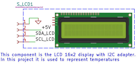
We can continue enhancing the previous LAB6 board adding another component: the LCD board subsystem composed of the LCD display and its I2C adapter. PCB implementation using KiCad: LAB7_PCB_Temp_meter_LCD.zip. Only one 4-pin header is required and the LCD goes connected on over the shield.
NOTE: Current CSD and DEE KiCad symbols, footprints and 3D tuned components are available in these three libraries: symbols.zip, footprints.zip and 3dmodels.zip, to be unzipped and placed in the corresponding 3rdparty user directory. Basically, in this introductory level the idea behind tunnig components is to enlarge their pads for easy soldering.
|
|
|
Fig. 7. The new component captured in KiCad schematic capture. |
The 3D view allows us to check that all the components are in place and the final appearance of the prototype.
|
|
|
Fig. 8. 3D top and lateral view of the prototype board completely wired. |
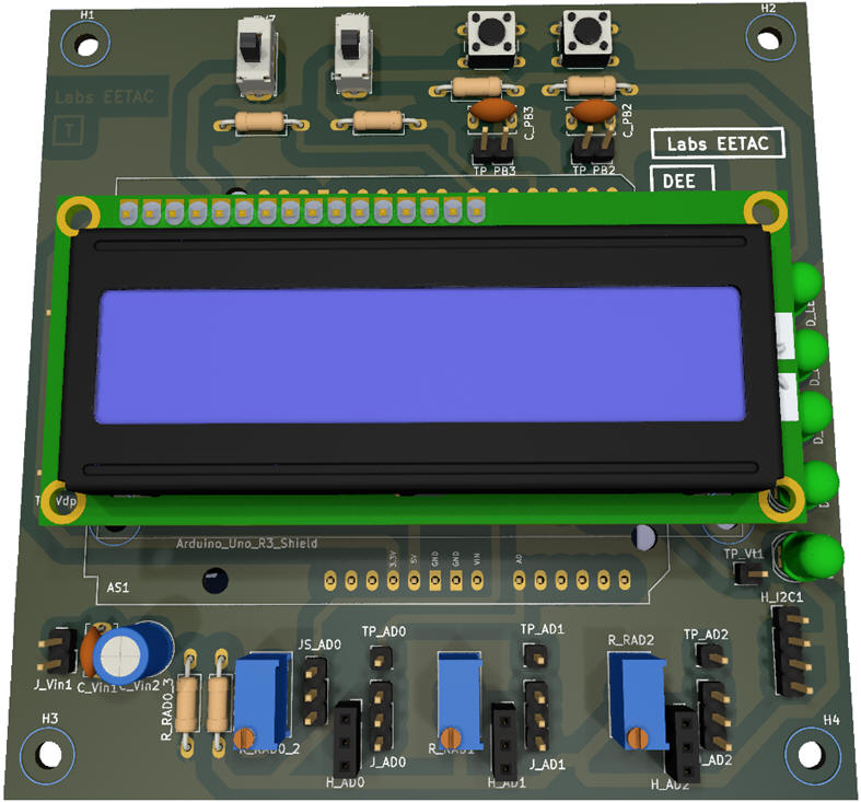
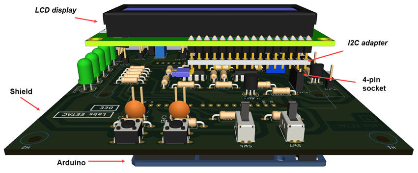
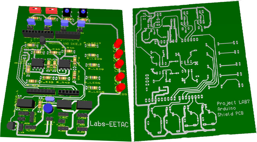
Fig. 9 is yet another version of the PCB using Multisim - Ultiboard (LAB7_PCB_v1.zip).
|
|
|
Fig. 9. 3D view of the prototype board completely wired. Only the cooper GND plane is yet to be connected. |
Experimentation and measurements
Once the components soldered, we can connect the I2C and the power supply to the LCD board and run the circuit downloading the code to the Arduino chip.
Another idea may be monitoring and decoding I2C frames send to the LCD display using VB8012 instrument.
| Specs | Planning | Dev. & Test | Prototype | 6. Report and postlab assignments |
This web page in itself is an example of report consisting of five sections.
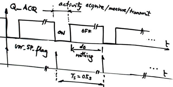
- Add another digital output, name it Q_ACT, and drive it ON while acquiring/measuring/transmitting and OFF while doing nothing, so that a pulsed rectangular waveform can be visualised on the oscilloscope. Check that its frequency is 2 Hz and measure its TON duration. Determine the maximum sampling frequency of this system.
|
|
|
Fig. 10. Waveform showing acquisition activity during an small fraction of the sampling period. |
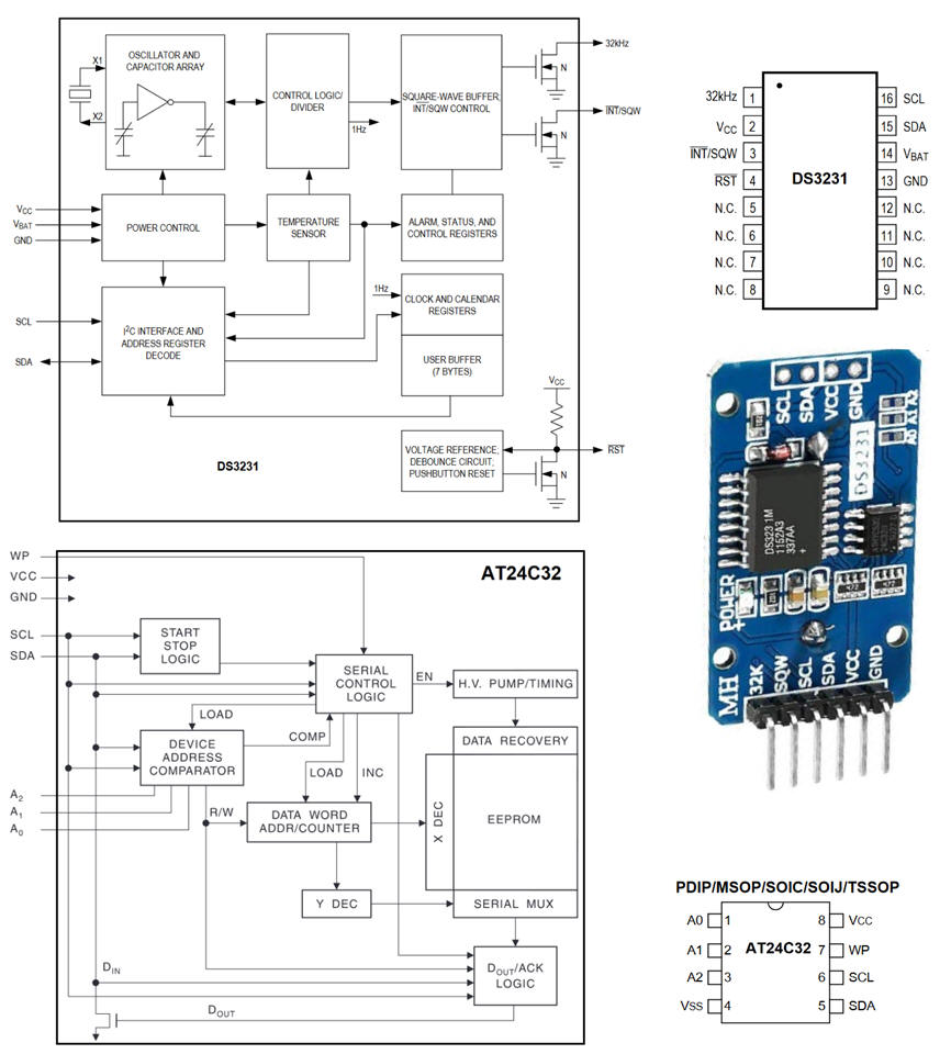
- Find examples of other sensors or actuators with I2C or SPI interface. For instance, this DS3231 real-time chip plus AT24C32 serial EPROM chip where to store temperature measurements every minute. The DS3234 is a similar RTC with SPI interface.
|
|
|
Fig. 10. I2C Breakout containing a RTC DS3231 and a 32 Kbit EEPROM. Find the board schematic and also the corresponding software libraries for communicating with the chips. |
| Home Contact Electronic devices and companies Books Magazines Instruments Digsys Library EETAC DEEL |

|
|
| Web activa des de 01/2023, @ F. J. Robert. Web editat amb Microsoft Expression Web 4. El contingut és material de referència per al disseny d'equips electrònics. Llicència:Reconeixement 4.0 Internacional de Creative Commons |